


Greensmaster eFlex 1800/2100 Page 4 -- 7 Electrical System
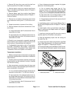
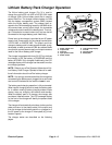
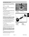
Startup
When the battery charger power switch is initially turned
on, the charger makes sure that the charger bus voltage
is at zero volts. If necessary, the charger discharges the
bus as a step in the startup process. This is typical in the
event that the charger power is cycled OFF and then
back ON.
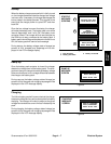
Once the bus voltage is correct for startup, the charger
will wake the battery pack. The battery pack runs some
internal diagnostics, and if all is OK, the battery main
contactor closes. The charger will then send a signal on
the CAN--bus to stay connected to the battery pack. If
battery pack internal diagnostics d etermine that allis not
OK, the battery pack will send a fault message.
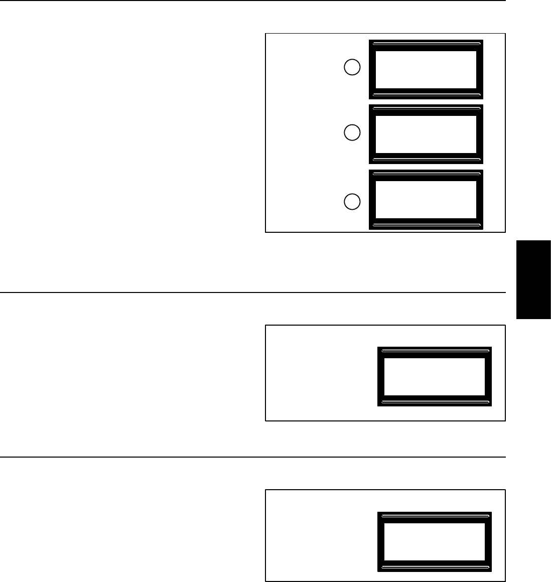
During startup, the battery voltage, state of charge (as
percent of fully charged) and amperage will be dis-
played in the LCD message display.
1. Bus discharge
2. Battery pack wake
3. Battery connected
Figure 4
Discharge Caps, Wait
XX.XV XX.X% X.XA
TORO Li+ CHARGER
Wake Asserted
XX.XV XX.X% X.XA
TORO Li+ CHARGER
Startup
Battery Accepted
XX.XV XX.X% X.XA
TORO Li+ CHARGER
1
2
3
STARTUP
MESSAGE
SCREENS
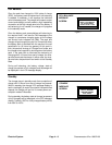
Ramp Up
Once the battery pack contactor is closed, the charger
detects the voltage level of the battery pack. The char-
ger bus is then pre--charged to match the batteryvoltage
to be sure that there is not a voltage differential between
the charger and battery pack.
During ramp up, the battery voltage, state of charge (as
percent of fully charged) and charging amperage will be
displayed in the LCD message display.
Figure 5
XX.XV XX.X% X.XA
TORO Li+ CHARGER
State 2, Ramp Up
RAMP UP
MESSAGE
SCREEN
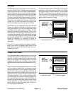
Charging
The lithium battery pack willcommunicatetothe charger
the proper voltage and current levels required for battery
charging. The charger will make its output at the given
voltage level and set the current limit as indicated by the
pack.
During charging, the battery voltage, state of charge (as
percent of fully charged) and charging amperage will be
displayed in the LCD message display.
Figure 6
State 3, CHARGING
XX.XV XX.X% X.XA
TORO Li+ CHARGER
CHARGING
MESSAGE
SCREEN
Electrical
System