


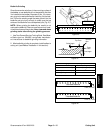
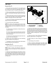
Greensmaster eFlex 1800/2100 Page 6 -- 23 Cutting Unit
Cutting Reel Assembly Removal (Fig. 34)
NOTE: Removal of the cutting reel can be completed
by removing the RH side plate from the cutting unit
crossmember. The LH side plate (including the reel
drive assembly) does not have to be removed from the
crossmember when using the following procedure.
CAUTION
Contact with the reel, bedknife or other cutting
unit parts can result in personal injury. Use
heavy gloves when removing the cutting reel.
1. Parkmachineonlevelsurface.Turnkeyswitchtothe
OFF position and remove key from the switch. Make
sure the traction lever is in the NEUTRAL position.
2. Disconnect the b attery pack (see Battery Pack Con-
nection in the General Information section of this chap-
ter).
3. Remove the cutting unit from the machine and place
cuttingunitonaflatworkarea.
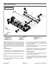
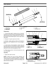
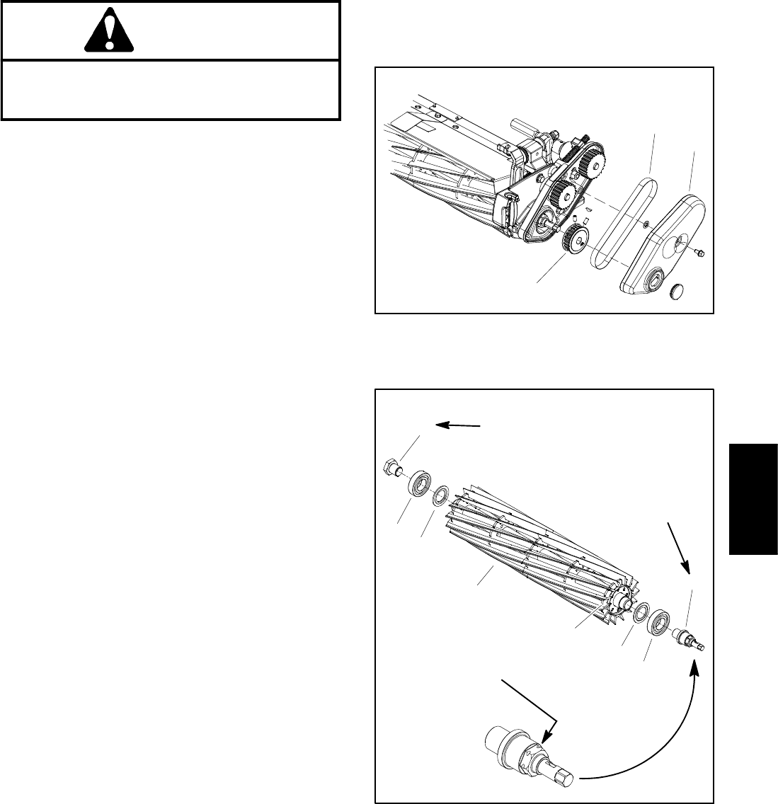
4. Remove reel drive cover and belt from reel drive as-
sembly. Then, remove reel pulley from reel drive shaft.
Refer to Reel Drive Assemblyinthe Service and Repairs
section of Chapter 4 -- Traction and Reel Drive System
for procedure to remove these components.
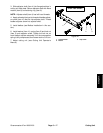
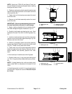
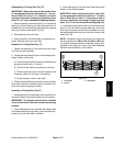
IMPORTANT: If reel drive shaft (item 4 in Fig. 36) is
to be loosened, use appropriate wrench or socket
on 1” hexsurfaceof shaft. Do notuse 1/2” extension
on end ofreel drive shaft when loosening or tighten-
ing drive shaft. The 1/2” hex is intended for backlap-
ping only.
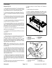
5. If bearings or seals are to be removed from cutting
reel, put a block of wood between the cutting reel blades
to prevent the reel from rotating. Loosen bearing lock
screw (RH threads) and reel drive shaft (LH threads) to
allow easier removal after reel assembly is removed
from cutting unit (Fig. 36).
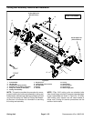
6. Remove the bedbar pivot bolt and washers from the
RH side plate. Note location of plastic and steel washers
for assembly purposes (see Bedbar Removal in this
section).
7. Loosen fasteners that secure front and rear rollers to
RH side plate (see Front Roller Removal and Rear Roll-
er Removal in this section).
8. Support cutting reel to prevent it from shifting or fal-
ling.
9. Remove shoulder bolts (item 4) and flange nuts (item
5) that secure the RH side plate to the cutting unit cross-
member. Remove the RH side plate from the reel shaft,
rollers, bedbar a nd cutting unit crossmember. Remove
RH pitch arm (item 7) a nd compression spring (item 3)
from RH side plate.
10.Carefully slide the cutting reel assembly (with
flocked seals, reel bearings, bearing lock screw andreel
drive shaft) from the LH side plate. Locate and remove
flat wire spring (item 14).
1. Reel drive cover
2. Belt
3. Reel pulley
Figure 35
1
2
3
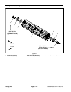
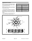
1. Cutting reel
2. Flocked seal (2 used)
3. Bearing (2 used)
4. Reel drive shaft
5. Bearing lock screw
6. Reel groove location
Figure 36
1
2
3
4
5
3
2
6
(Right Hand Threads)
90 to 110 ft--lb
(123 to 149 N--m)
90 to 110 ft--lb
(123 to 149 N--m)
(Left Hand Threads)
Usethis1”hexsurface
when removing or
installing reel drive shaft
Cutting Unit