


Greensmaster eFlex 1800/2100Page 4 -- 20Electrical System
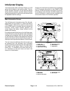
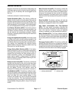
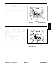
Diagnostics Screen
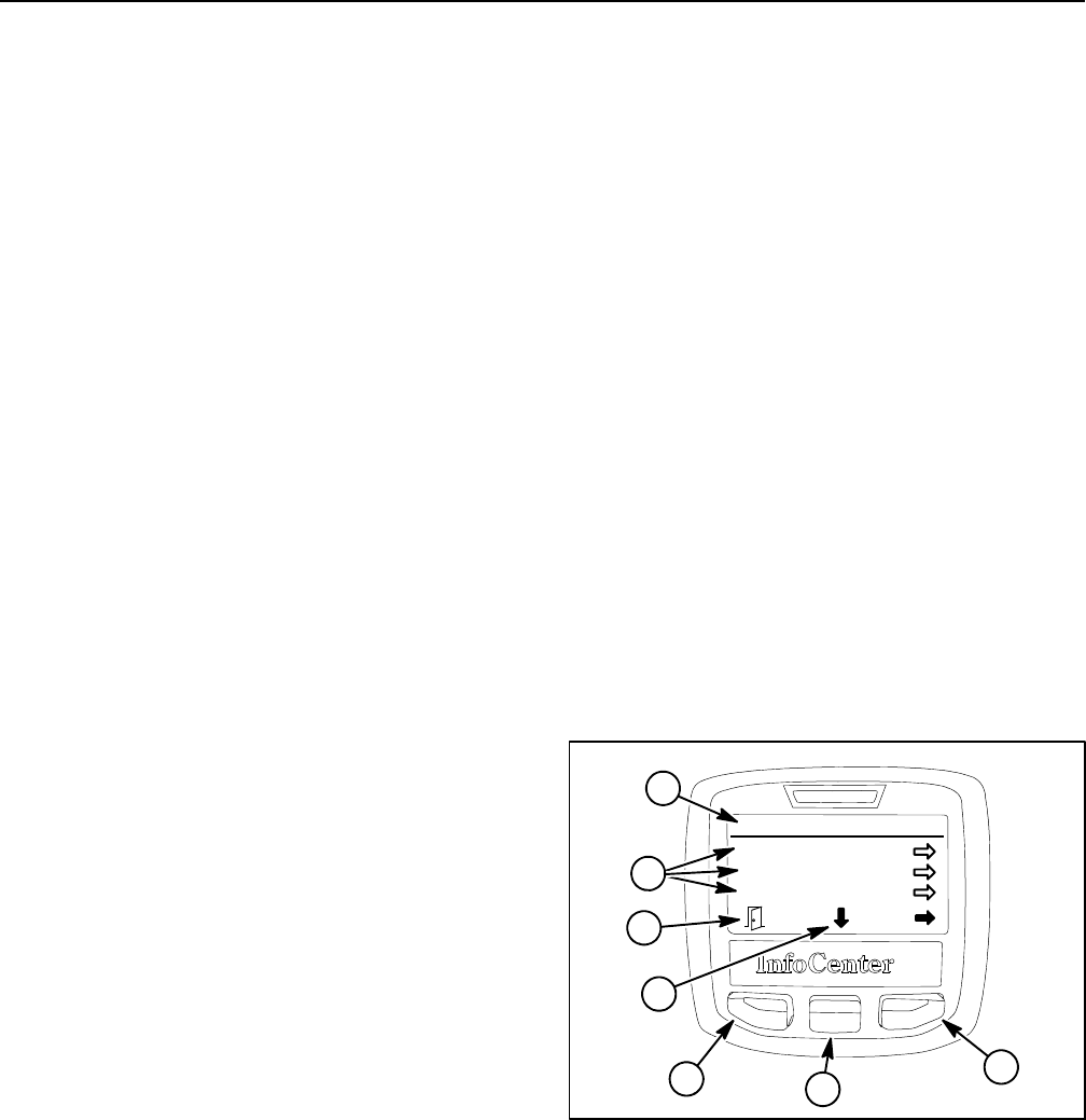
The diagnostics screen (Fig. 22) lists the various states
of machine electrical components. The diagnostics
screen should be used to check operation of machine
switches and controls.
IMPORTANT: When using the diagnostics screen,
make sure to have machine on kickstand to prevent
unexpected machine movement as switches and
controls are moved.
NOTE: Some of the component states may have de-
scription available when using the diagnostics screen.
If an arrow icon is shown on the screen, pressing the
choose menu item button will display the description if
available.
The diagnostics screen includes the following:
D Key On identifies that the key switch is in the RUN
position.
D Key Start indicates that the key switch is in the
START position or not. NOTE:The key start position can
be verified in the diagnostics screen by rotating the
switch to the START position. The motor will re--initial-
ize.
D PBrake Latch identifies that the parking brake latch
is engaged or not.
D EZ Turn indicates whether the EZ turn operation is
ON or OFF. NOTE: The EZ turn switch and EZ turn sen-
sor are in series so both switch and sensor have to be
ON (switch ON with the cutting unit raised for a turn) for
the diagnostics screen to identify the EZ Turn operation
as being ON. If either the switch is OFF or the sensor is
OFF (cutting unit lowered to the ground), the EZ Turn
operation will be OFF.
D Traction identifies that the traction lever is engaged
or not engaged.
D Reel Enable indicates whether the cutting reel is en-
gaged or not engaged.
D Throttle identifies the throttle control setting (in
volts) that is used by the TEC controller to determine
electric motor speed. Rotating the speed wheel should
change the set ting. Voltage for throttle settings should
range from 0.35to 4.80 VDC depending on speedwheel
location.
D Target RPM lists the desired electric motor RPM
based on the speed control setting. Rotating the speed
wheel should change the setting.
D Motor RPM identifies the actual e lectric motor RPM.
The motor RPM should be very close to the Target RPM.
D 12V Supply indicates the supplied voltage available
for the 12 VDC circuits (InfoCenter, EZ turn sensor). The
12V Supply should typically be slightly higher than 12.0
VDC.
D 5V Supply indicates the supplied voltage available
for the 5 VDC circuit (speed control). The 5V Supply
should typically be slightly higher than 5.0 VDC.
D CAN bus identifies whether the machine commu-
nication bus status is normal or not.
To return to the main menu screen from the diagnostics
screen, press the back button (left button).
1. Diagnostics menu
2. Diagnostics items
3. Move to menu items
4. Choose menu item
5. Back button
Figure 22
Diagnostics
Key On:
Key Start:
PBrake Latch:
ON
OFF
ON
1
5
3
4
5
2
3