Greensmaster eFlex1800/2100Page 5 -- 4Chassis and Controls
Service and Repairs
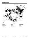
Handle Assembly
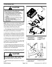
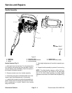
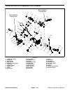
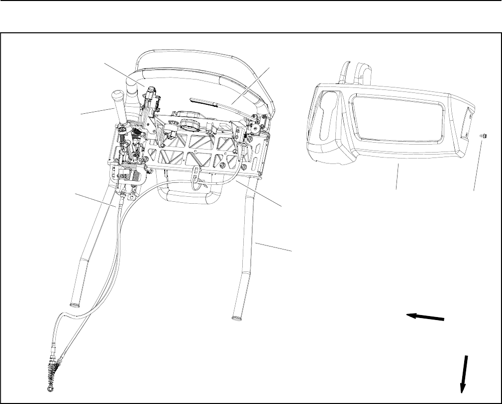
Figure 2
1. Brake lever
2. Brake cable
3. Handle
4. Reel clutch cable
5. Traction and reel drive lever
6. Throttle assembly
7. Console cover
8. Washer head screw (4 used)
RIGHT
7 8
2
3
6
1
5
4
FRONT
Handle Removal (Fig. 2)
1. Parkmachineon level surface. Turnkeyswitch to the
OFF position and remove key from the switch. Discon-
nect the battery pack (see Battery Pack Connection in
the General Information section).
2. Remove console cover from handle assembly.
3. Disconnect reel clutch and brake cables from trans-
mission (see Cable Replacement in this section).
4. Label all wire harness connections for assembly pur-
poses. Disconnect wire harness connections from elec-
trical components on handle. Position wire harness
away from handle.
5. Note height adjustment of handle for assembly pur-
poses.
6. Support handle assembly to prevent it from moving.
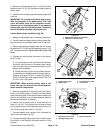
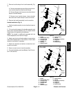
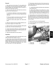
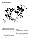
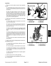
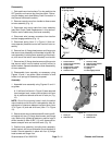
NOTE: The offset handle clamps on eFlex 2100 ma-
chines are m ounted on the outside of the side plates
(Fig. 3). On eFlex 1800 machines, the offset handle
clamps are mountedon the inside ofthe side plates (Fig.
4).


