Greensmaster eFlex 1800/2100Traction and Reel Drive System Page 3 -- 38
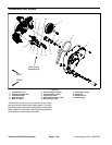
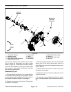
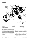
Transmission Drum Drive System
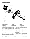
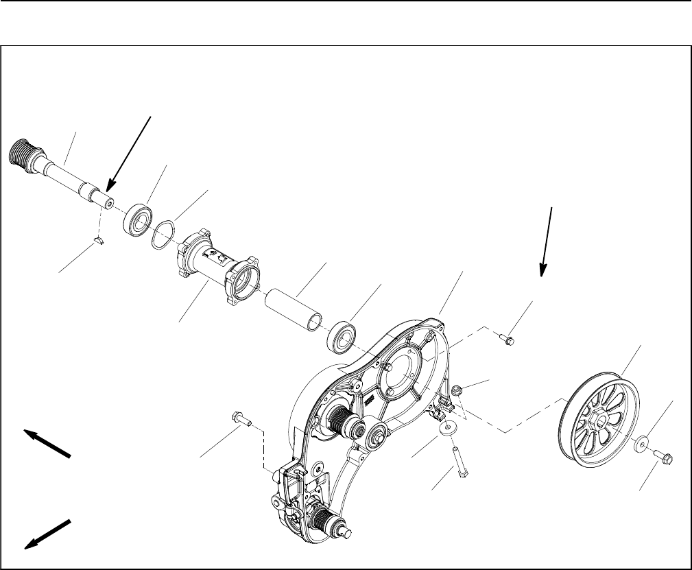
Figure 45
1. Transmission housing
2. Extension housing
3. Ball bearing (2 used)
4. Driven pulley (traction drum drive)
5. Hardened washer (2 used)
6. Driven pulley
7. Spacer
8. Wave washer
9. Woodruff key
10. Washer head screw (4 used)
11. Flange nut
12. Flange head screw (2 used)
13. Cap screw
FRONT
RIGHT
6
5
5
2
4
3
3
1
7
8
9
10
11
12
12
13
See text for
tightening
procedure
Lubricant
Antiseize
Transmission removal from the machine is not neces-
sary to service the transmission drum drive system
shown in Figure 45. Transmission drum drive compo-
nents can be accessed by removing the battery pack
from the frame, removing the transmission cover and
then removing the drive belt.
Disassembly (Fig. 45)
1. Parkmachineon level surface. Turnkeyswitch to the
OFF position and remove key from the switch. Discon-
nect the battery pack (see Battery Pack Connection in
the General Information section of this chapter).
2. Remove transmission drive belt (see Transmission
Drive Belt in this section).
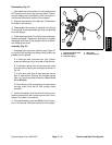
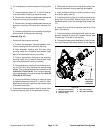
3. Remove flange head screw (item 12) and hardened
washer (item 5) t hat secure driven pulley (item 6) to
shaft. Slide pulley from shaft. Locate and retrieve wood-
ruff key (item 9).
4. Remove drum drive belt from machine (see Drum
Drive Belt in this section).
5. Slide traction d rum drive driven pulley (item 4) from
extension housing.
6. If necessary, remove ball bearings (item 3), spacer
(item 7) and wave washer (item 8) from extension hous-
ing.


