


Greensmaster eFlex 1800/2100 Page 4 -- 37 Electrical System
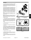
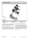
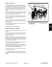
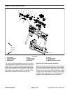
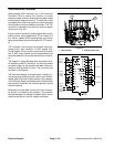
EZ Turn Sensor
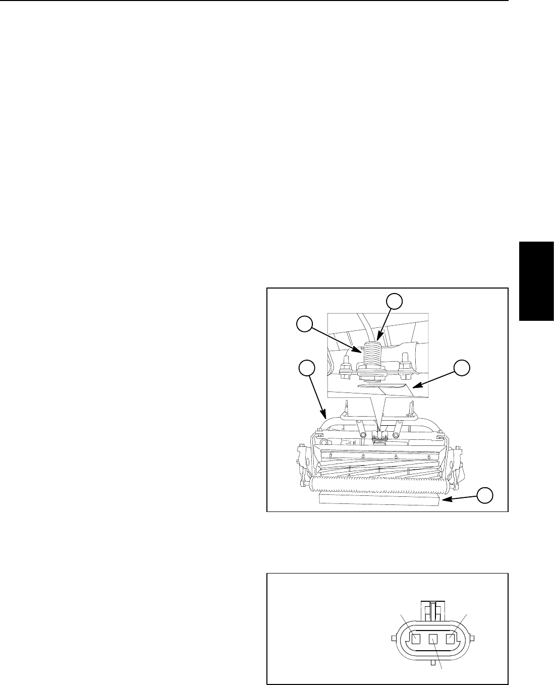
The EZ turn sensor is a normally open proximity sensor
that mounts to a bracket mounted to the cutting unit roll
frame (Fig. 47). The sensing plate for the sensor is a tar-
get plate attached to the top of the cutting unit assembly.
The TECcontroller monitors theoperation of theEZ turn
sensor.
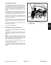
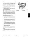
When the traction unit is supported on the traction drum
with the cutting unit supported by both front and rearroll-
ers on level ground, the target end of the EZ turn sensor
is positioned away from the target plate on the cutting
unit so the sensor is open. The EZ turn sensor is moved
toward the cutting unit target plate when the cutting unit
is raised for turning, causing the sensor to close.
NOTE: The EZ turn sensor LED should be illuminated
whenever the machine is operational (key switch in the
RUN position) and the cutting unit is raised.
NOTE: TheEZturnfunctionisonlyactivewhenthema-
chine is being operated with the cutting unit engaged.
Also, the EZ turn switch and EZ turn sensor are in series
so both switch and sensorhave to be ON for the EZ Turn
function to be ON. If either the switch or the sensor is
OFF, the EZ Turn function will be OFF.
NOTE: Information on EZ turn sensor adjustment is in-
cluded in the eFlex Operator’s Manual.
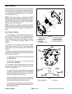
Sensor Testing
1. Park machine on level surface and place traction le-
ver in the NEUTRAL position.
2. Turn key switch to the START position to wake up the
machine and then turn key switch to the RUN position.
3. Check LED on cable end of EZ turn sensor:
A. The sensor LED should not beilluminated when
the cutting unit is being supported by both front and
rear rollers on level ground.
B. The sensor LED should be illuminated when the
cutting unit is raised (handle pushed down).
4. If the EZ turn sensor LED did not function correctly:
A. Make sure that EZ turn sensor is properly ad-
justed (see Operator’s Manual). If necessary, adjust
sensor and return to step 4 above.
B. Make sure key switchis OFF andthen disconnect
the EZ turn sensor connector from the machine wire
harness.
C. TurnkeyswitchtotheSTARTpositiontowakeup
the machine and then turn key switch to the RUN
position.
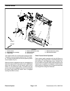
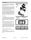
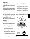
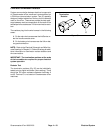
D. Connect multimeter common (--) test probe to
harness connector terminal C (black wire) and sec-
ond test probe to harness connector terminal A (pink
wire) (Fig. 48). Verify with the multimeter that har-
ness connector has 12 VDC circuit voltage present.
E. If sensor connector has circuit voltage present
and sensor LED did not function, replace EZ turn
sensor. Adjust sensor after installation (refer to Op-
erator’s Manual).
5. After EZ turn sensor testing is complete, plug sensor
connector into machine wire harness.
6. Connect the battery pack (see Lithium Battery Pack
Connection in the General Information section of this
chapter).
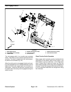
1. EZ turn sensor
2. Target plate
3. Cutting unit roll frame
4. Sensor LED location
5. 1.5” block under roller
Figure 47
1
2
3
4
5
Figure 48
PINK wire at A
ORANGE wire at B
BLACK wire at C
A
B
C
WIRE HARNESS CONNECTOR FOR SENSOR
Electrical
System