


Greensmaster eFlex 1800/2100 Traction and Reel Drive SystemPage 3 -- 41
4. Remove RH drum drive cover and drive belt from
machine ( see Drum Drive Belt in this section).
5. Remove electric motor from machine (see Electric
Motor in the Service and Repairs section of Chapter 4
-- Electrical System).
6. Remove battery pack from machine (see Battery
Pack in the Service and Repairs section of Chapter 4 --
Electrical System).
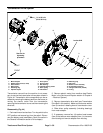
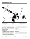
7. Remove four (4) washer head screws (item 8) that
secure extension housing (item 17) to RH drum hous-
ing.
8. Support transmission to prevent it from falling.
9. Remove fasteners that secure transmission to ma-
chine frame.
A. Flange head screw (item 2) that secures front of
transmission to frame.
B. Cap screw (item 13), hardened washer (item 14)
and flange head screw (item 16) that secure rear of
transmission to frame.
10.Carefully move transmission assembly toward left
side of machine until extension housing is clear of RH
drum housing. Lift transmission from machine.
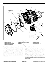
11.To disassemble transmission, refer to Transmission
Drive Belt, Transmission Idler System, Transmission
Reel Drive System, Transmission Drive System and
Transmission Drum Drive System in this section.
Transmission Installation
1. Make sure that all internal transmission components
are correctly installed before transmission is installed to
machine frame.
2. Carefully install transmission assembly toward right
side of machine so that extension housing is inserted
into RH drum housing.
3. Align transmission mounting holes with frame and
RH drum housing. Install and finger tighten fasteners to
secure transmission to machine.
A. Four (4) washer head screws (item 8) that secure
extension housing (item 17) to RH drum housing.
B. Cap screw (item 13), hardened washer (item 14)
and flange head screw (item 16) that secure rear of
transmission to frame. Make sure that washer (item
14) is below frame tube.
C. Flange head screw (item 2) that secures front of
transmission to frame.
4. Once all fasteners have been installed, fully tighten
fasteners in the following order:
A. Four (4) washer head screws (item 8). First,
torque all screws from 15 to 40 in--lb (1.7 to 4.5
N--m). Then, using an alternating crossing pattern,
torque screws from85 to 95 in--lb (9.6 to10.7 N--m).
B. Cap screw (item 13) and flange head nut (item
16) that secure rear of tr ansmission to frame.
C. Flange head screw (item 2) that secures front of
transmission to frame.
5. Install battery pack to machine (see Battery Pack in
the Service and Repairs sectionofChapter 4 -- Electrical
System).
6. Install electric motor to transmission (see Electric
Motor in the Service and Repairs section of Chapter 4
-- Electrical System).
7. Install drum drive belt and RH drum drive cover to
machine (see Drum Drive Belt in this section).
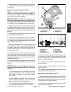
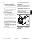
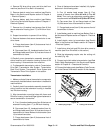
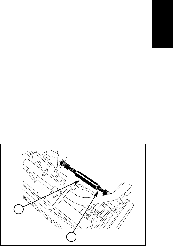
8. Slide the telescoping coupler onto the cutting unit
hex shaft (Fig. 48).
9. Connect reel clutch cable to transmission (see Reel
Clutch Cable Replacement in the Service and Repairs
section of Chapter 6 -- Chassis and Controls).
10.Connect the batterypack (see Battery PackConnec-
tion in the General Information section of this chapter).
1. Telescoping coupler 2. Cutting unit hex shaft
Figure 48
1
2
Traction and Reel
Drive System