Greensmaster eFlex 1800/2100 Traction and Reel Drive SystemPage 3 -- 15
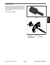
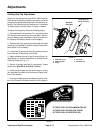
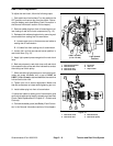
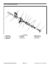
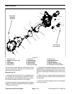
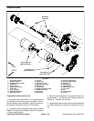
Disassembly (Fig. 18)
1. Parkmachineonlevelsurface.Turnkeyswitchtothe
OFF position and remove key from the switch. Discon-
nect the battery pack (see Battery Pack Connection in
the General Information section of this chapter).
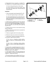
2. Remove reel drive bearing housing from reel drive
housing (see Reel Drive Assembly in this section).
3. Removeretaining ring (item1) from bearing housing.
4. Slide reel input shaft assembly from bearing hous-
ing. Remove wave washer (item 5) from bearing hous-
ing.
IMPORTANT: When removing flex coupler (item 12)
from reel input shaft (item 2), do not mar outer sur-
face of coupler (e.g. grasping with pliers or mount-
ing in vise) as coupler may be damaged and fail
prematurely.
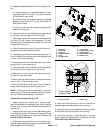
5. Support flexcoupler (item 12) to preventit from being
damaged during spring pin removal. Push spring pin
from flex coupler and reel input shaft. Slide coupler from
shaft and discard spring pin.
6. Remove retaining ring (item 9) from shaft. Then re-
move flat washer (item 8), wave spring (item 7 ) and
flocked bearing shield (item 6) from shaft. Note orienta-
tion of flocked shield for assembly purposes.
7. Press bearings and bearing spacer from shaft if nec-
essary. Discard bearings if removed.
8. Clean all bearing housing components.
Assembly (Fig. 18)
1. Ifbearings were removed from reelinputshaft,install
new bearings onto shaft. Press first bearing fully onto
shaft. Position spacer on shaft and then press second
bearing onto shaft.
2. Install flocked bearing shield (item 6), wave spring
(item 7) and then flat washer (item 8) onto reel input
shaft. Secure components to shaft with retaining ring
(item 9). It may be necessary to drive the retaining ring
onto the input shaft with a tubular tool and mallet. Make
sure that retaining ring is f ully seated into shaft groove
after installation.
3. Place wave washer (item 5) into bearing housing.
4. Fill cavity between bearings with Mobil High Temper-
ature XHP--222 g rease (or equivalent).
5. Install reel input shaft assembly into bearing housing
andsecurewithretainingring(item1).
IMPORTANT: When installing flex coupler (item 12)
onto reel input shaft (item 2), do not mar outer sur-
face of coupler (e.g. grasping with pliers or mount-
ing in vise) as coupler may be damaged and fail
prematurely.
6. Slide flex coupler onto reel input shaft, support cou-
pler to prevent it from being damaged during spring pin
installation. Install new spring pin into coupler to secure
it t o shaft.
7. Install reel drive bearing housing to reel drive hous-
ing (see Reel Drive Assembly in this section).
8. Connectthe battery pack(see Battery Pack Connec-
tion in the General Information section of this chapter).
Traction and Reel
Drive System


