


Greensmaster eFlex 1800/2100Page 6 -- 18Cutting Unit
Front Roller
Removal (Fig. 25)
1. Parkmachineon level surface. Turnkeyswitch to the
OFF position and remove key from the switch. Make
sure the traction lever is in the NEUTRAL position.
2. Disconnect the battery pack (see Battery Pack Con-
nection in the General Information section of this chap-
ter).
3. Remove the cutting unit from the machine and place
on a level working surface. Use appropriate support to
raise front roller from work surface.
4. Loosen cap screw (item 1) that secures the front roll-
er shaft to each front height--of--cut arm.
5. On one of the height --of--cut arms, remove HOC nut
(item 7), HOC washer (item 6) and plow bolt(item 4) that
secure HOC arm to the cutting unit side plate. Remove
the HOC arm from the cutting unit.
6. Slide the front roller assembly from the remaining
HOC arm on the cutting unit.
7. If necessary, remove the second HOC arm from the
cutting unit.
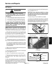
Installation (Fig. 25)
1. Place cutting unit on a level working surface and use
appropriate support to support front of cutting unit.
2. Inspect condition of HOC screws (item 5) in both
HOC arms. If screwreplacement is necessary, applyan-
tiseize lubricant to threads of new HOC screw. Thread
newHOCscrewintoHOCarm.
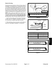
NOTE: When assembling HOC arms to side plates,
make sure that ring on HOC screw fits into the notch on
thesideplate.
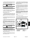
3. If both HOC arms were removed from cutting unit
side plate, position one of the arms to side plate. Secure
arm to side plate with plow bolt (item 4), HOC washer
(item 6) and HOC nut (item 7). Tab on HOC washer
should be positioned into HOC arm slot and orientated
down toward the roller.
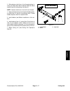
4. Slide front roller shaft into arm attached to the cutting
unit. Slide second HOC arm onto the other end of roller
shaft. Secure second arm to cutting unit side plate with
plow bolt (item 4), HOC washer (item 6) and HOC nut
(item 7).
5. Center front roller to the cutting reel and secure to
HOC arms with cap screws (item 1).
6. Adjust cutting unit (see Cutting Unit Operator’s
Manual).
7. Install cutting unit to machine.
8. After all necessary adjustments have been made,
connect the battery pack (see Battery Pack Connection
in the General Information section of this chapter).
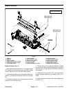
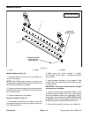
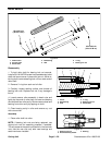
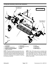
1. Cap screw
2. HOC arm
3. Front roller assembly
4. Plow bolt
5. HOC screw
6. HOC washer
7. HOC nut
Figure 25
Antiseize
Lubricant
1
2
3
4
5
6
7
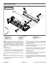
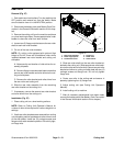
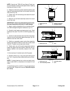
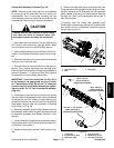
1. Front roller assembly
2. HOC arm
3. HOC screw
4. HOC washer & nut
Figure 26
2
1
3
4