


Performance Verification
4-28
AWG510 & AWG520 Service Manual
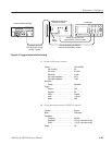
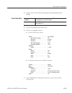
a. Initialize the AWG500–Series Waveform Generator controls:
Push UTILITY (front–panel)!
System (bottom)!Factory Reset (side)!OK (side).
b. Set gated mode: Push SETUP (front–panel)!Run Mode
(bottom)!Gated (side).
c. Select the waveform file: Load the MODE.WFM as referring to the
procedures on page 4–15.
4. Turn on the AWG500–Series Waveform Generator CH1 output: Push the
RUN and CH1 OUT buttons so that the LEDs above the RUN button and
CH1 output connector light.
5. Check gated mode with manual trigger: Hold down the AWG500–Series
Waveform Generator FORCE TRIGGER button, and check that the
oscilloscope continuously displays a sine wave while you are holding down
the FORCE TRIGGER button.
6. Check gated mode with gate signal:
a. Change the oscilloscope horizontal sweep setting to 20 ms/div.
b. Set the oscilloscope trigger source to CH2.
c. Apply gate signal: Turn on the function generator output.
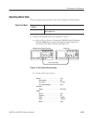
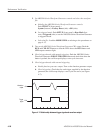
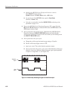
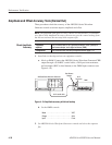
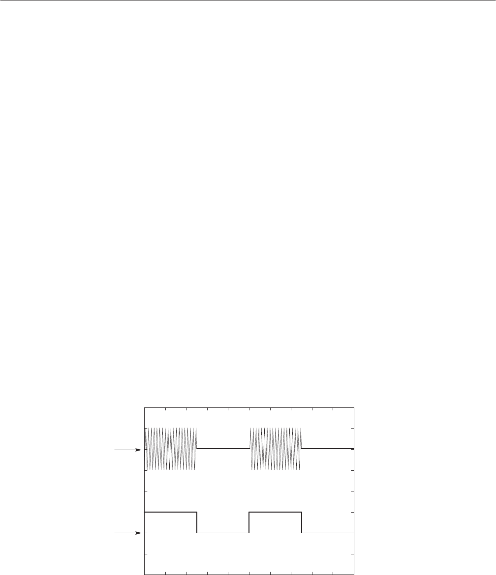
d. Check gated mode with positive gate signal: Check that the oscilloscope
displays a sine wave while the function generator gate signal amplitude
is equal to or larger than 1 V (see Figure 4–8).
Wavefor m
output
CH1
Gate
signal
CH2
Figure 4-8: Relationship between gate signal and waveform output