


Performance Verification
4-52
AWG510 & AWG520 Service Manual
Event Input and Enhanced Mode Tests
These procedures check the event input signals and enhanced mode operation.
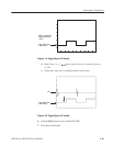
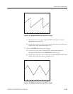
NOTE. The event input check with strobe off and strobe input check are struc-
tured as a continuous test. After Check Event Input with Strobe Off, the next test
uses the connections and oscilloscope settings from the last test.
Equipment
required
A 50ĂΩ coaxial cable, an oscilloscope, and customĆmade ground
closure.
Prerequisites The AWG500-Series Waveform Generator must meet the prerequisites
listed on page 4-13.
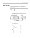
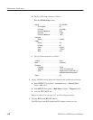
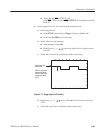
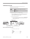
1. Install the test hookup and set test equipment controls:
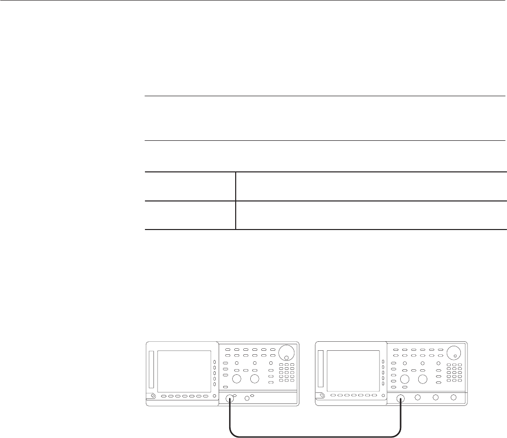
a. Hook up the oscilloscope: Connect the AWG500–Series Waveform
Generator CH1 output connector through the coaxial cable to the
oscilloscope CH1 input connector (see Figure 4–21).
Oscilloscope
50 W coaxial cable
AWG500 Series Waveform Generator
Figure 4-21: Event input and enhanced mode initial test hookup
b. Connect the ground closure: Connect the ground closure to the EVENT
IN connector on the AWG500–Series Waveform Generator rear panel.
c. Set the oscilloscope controls:
Vertical . ........................ CH1
CH1 coupling . ............... DC
CH1 scale . ................. 0.2V/div
CH1 input impedance . ......... 50W
Horizontal
Sweep . .................... 0.5ms/div
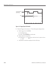
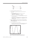
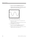
Check Event Input with
Strobe Off