


Adjustment Procedures
5-18
AWG510 & AWG520 Service Manual
This procedure adjusts the AWG500 noise output level.
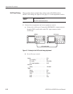
Equipment
Required
One spectrum analyzer (Item 1)
One 50 W coaxial cable (Item 5)
One adapter; BNC female to N male (Item 6)
One DC block (Item 7)
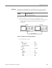
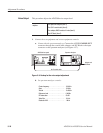
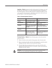
1. Connect the test equipment and set test equipment controls:
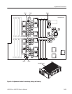
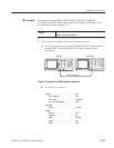
a. Connect the the spectrum analyzer: Connect the AWG500 NOISE OUT
connector through the coaxial cable, adapter, and DC Block to the input
connector on the spectrum analyzer (see Figure 4–37).
AWG500 front panel Spectrum Analyzer
50 W coaxial cable
497P
Adaptor and
DC Block
Figure 5-9: Hookup for the noise output adjustment
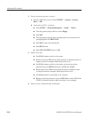
b. Set spectrum analyzer controls:
Centerfrequency ................. 100MHz
Span . ......................... 10MHz
Vertical . ........................ 10dB/div
Referencelevel................... 0dB/div
RF attenuation . .................. 20dB
Video filter . ..................... 10kHz
Resolution BW . .................. 1MHz
Noise Output