


Removal and Installation Procedures
6-46
AWG510 & AWG520 Service Manual
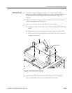
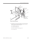
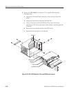
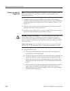
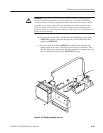
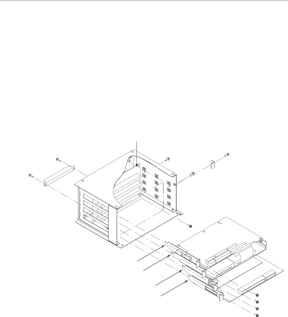
4. Remove the CPU Board: Use Figure 6–22 as a guide while doing the
following steps:
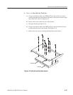
a. Unplug the VGA and COM1 connectors on the left side of the CPU
board.
b. Unplug the interconnect cable from the flash disk.
c. Using a screwdriver with a size Phillips #2 tip, remove the screw
securing the CPU board to the frame with a retainer on the the right side
of the unit.
d. Remove the screw on the left side of the CPU board.
e. Grasp the board and slide it out of the unit.
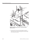
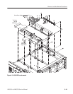
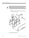
CPU board
Hard disk &
Flash disk
LAN board
A30 GPIB board
Backplane
Figure 6-22: CPU, HDD/Flash disk, LAN, and GPIB boards removal