


Adjustment Procedures
5-14
AWG510 & AWG520 Service Manual
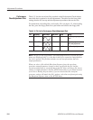
H Turn the general purpose knob to find the upper limit for the
waveform corrupted area. Note the value as N2.
H Calculate (N1+N2)/2–28 and set the value to it. That is the proper
setting. For example, if N1=40 and N2=50, then set the value to 17.
The following step 5 is for the AWG520 only. For the AWG510, go to the step 6.
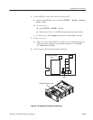
5. Adjust CH 2 DAC clock timing: (for AWG520 only)
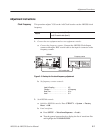
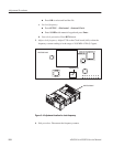
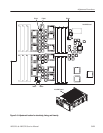
a. Modify the AWG500 hookup: Disconnect the coaxial cable on the CH 1
output connector and connect it to the CH 2 output connector.
b. Set AWG500 controls: Press CH2 Delay.
c. Adjust timing:
H Turn the general purpose knob to find the setting of output wave-
form corrupted. The value should be near 40.
H Turn the general purpose knob to find the lower limit for waveform
corrupted area. Note the value as N1.
H Turn the general purpose knob to find the upper limit for waveform
corrupted area. Note the value as N2.
H Calculate (N1+N2)/2–28 and set the value to it. That is proper
setting.
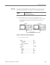
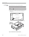
6. Save the settings: Press Save.
7. End procedure: Disconnect the oscilloscope.