


Removal and Installation Procedures
6-64
AWG510 & AWG520 Service Manual
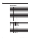
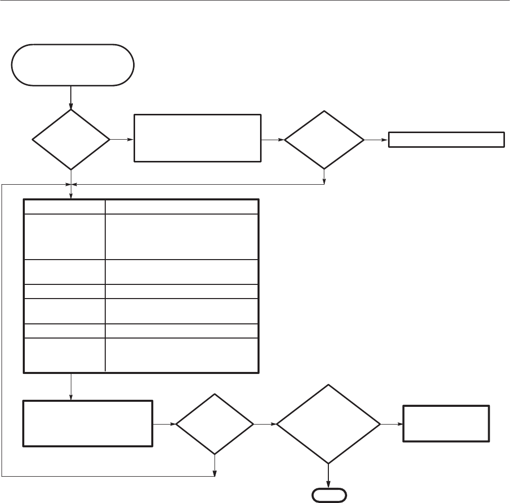
Diagnostics Related module
System
A40 Clock board (page 6-39)
Run mode
Check all cables. Be sure every
cable is attached securely. Replace
the module indicated in the
diagnostics. Run all diagnostics.
Can the
data be read or
written from/to
formatted floppy
disk?
Replace the floppyĆdisk
drive module
(page 6-31).
Done.
Clock
No
Yes
Does the
display report
any errors?
Are any
failures
reported?
The waveform generator is ok.
Select the extended diagnostics
menu and run all the test suites (the
discussion of the Diagnostics on
page 6-55 explains how to do this).
Yes
No
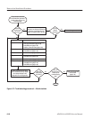
This procedure assumes
that the waveform generator is
up and running and you can
read the display.
Output
Yes
No
A71/72 Output board (page 6-37)
A50 AWG board (page 6-40)
A50 AWG board (page 6-40)
A30 GPIB board (page 6-39)
A60 Memory board (page 6-35)
A50 AWG board (page 6-40)
A30 GPIB board (page 6-39)
Does the
display report
any errors?
No
Yes
CPU board (page 6-39)
A20 Front Panel board (page 6-39)
A30 GPIB board (page 6-39)
A10/A11 Connector board (page 6-34)
Sequence Memory
Waveform Memory
A50 Memory board (page 6-40)
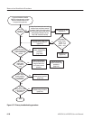
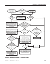
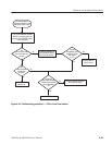
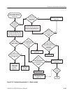
Figure 6-37: Troubleshooting procedure 4 Ċ Module isolation