


Removal and Installation Procedures
6-52
AWG510 & AWG520 Service Manual
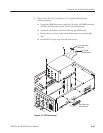
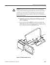
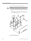
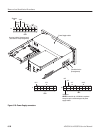
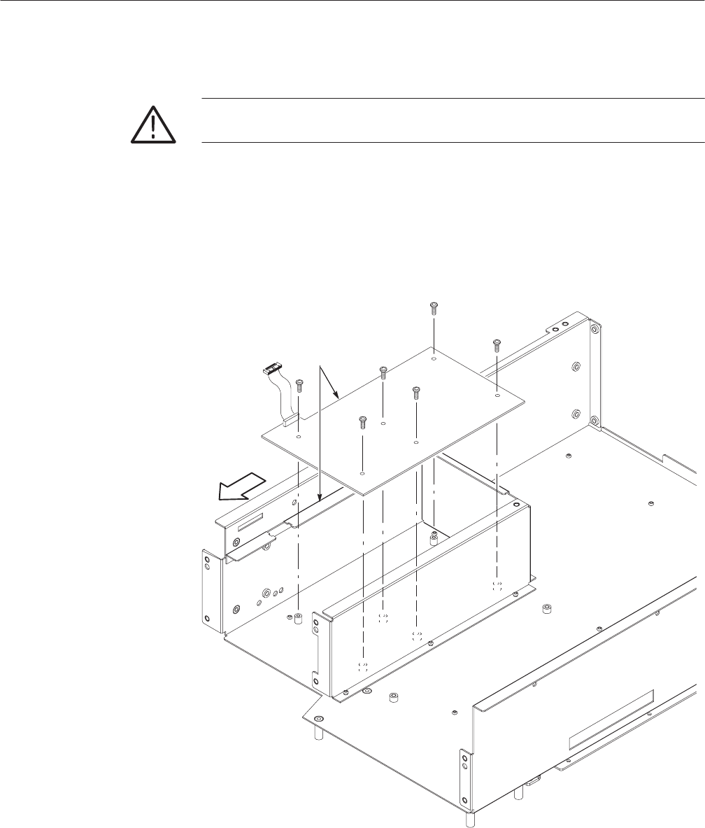
5. Remove the display supply board: Use Figure 6–25 as a guide.
CAUTION. If any RTV Silicon is removed from the generator, it must be replaced
in order to maintain the warranted characteristics for random vibration.
a. Remove the six screws that mount the display-driver board to the main
chassis.
b. Grasp the display driver board. Work from the front and top to tilt the
board so its right edge is up and its left side is down and lift it out of the
top of the generator’s main chassis.
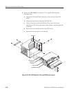
Move circuit boar d
forward to clear
main chassis.
Figure 6-25: Display Driver Board removal