


Specifications
1-4
AWG510 & AWG520 Service Manual
Electrical Specification
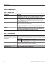
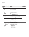
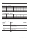
Table 1-2: Operation modes
Characteristics Description
Continuous Waveform is continuously output in this mode. When a sequence is defined, waveforms
are sequentially or repeatedly output in the order defined by the sequence. The extended
sequence functions such as trigger input, event jump, etc. are neglected in this mode.
Triggered Waveform is output only once when a trigger event is created. A trigger signal is created by
the external trigger input signal, GPIB trigger command, and/or pressing the front-panel
FORCE TRIGGER button. The extended sequence functions such as trigger input, event
jump, etc. are neglected in this mode.
Gated The waveform is output as the same way as in the continuous mode only when the gate is
opened. The gate is opened by the gated signal.
Note that the output is made from the top of the first waveform for every gate periode. The
clock signal continuously output from the connector even outside the gate periode.
Enhanced The waveforms are sequentially or repeatedly output according to the procedures defined
in the sequence. All extended functions such as trigger input, event jump, etc. are effective
and waveforms are controlled for output by this functions in this mode.
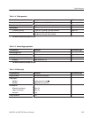
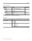
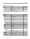
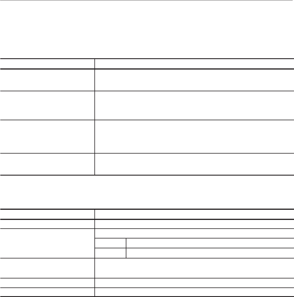
Table 1-3: Arbitrary waveforms
Characteristics Description
Waveform memory Memory length: 4,194,048 words (10 bits/1 word)
Marker memory Memory length:
AWG510
4,194,048 words (2 markers 1 bit / 1 word)
AWG520
4,194,048 words (4 markers 1 bit / 1 word)
Sequence memory Maximum 8000 steps
The sequence operates for both CH1 and CH2 in the AWG520.
Sequence counter 1 to 65536, or Infinite
Waveform data points Multiple of 4 in the range from 256 to 4,198,048 points