


Specifications
1-8
AWG510 & AWG520 Service Manual
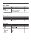
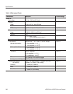
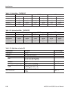
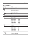
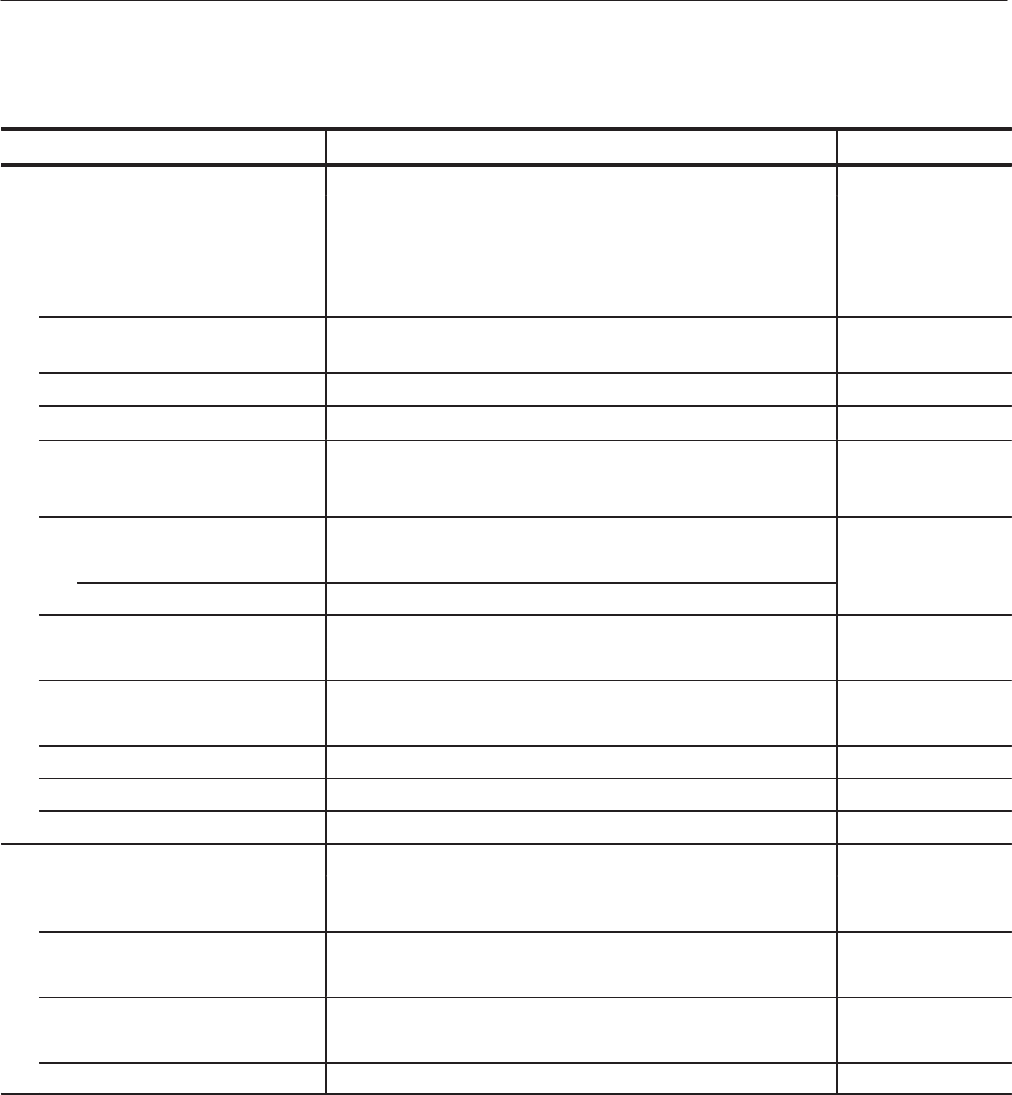
Table 1-8: Auxiliary outputs
Characteristics Description PV reference page
Marker
4
Number of markers
AWG510 2 ( Note that the markers are not additionally installed even
when the Option 03 is installed. )
AWG520 4
Level (Hi/Lo) -2.0 V to +2.0 V, into a 50 W load
-4.0 V to +4.0 V, intoa1MW load
Resolution 0.05 V
* Accuracy
Within "(0.1 V +5 % of setting)
Page 4-65
Rise and fall times (10 % to 90 %),
Typical
0.5 ns (1 V
pĆp
, Hi: +0.5 V, Lo: -0.5 V)
1.0 ns (2 V
pĆp
,Hi: +1 V, Lo: -1 V)
2.0 ns (4 VpĆ
p
, Hi: +2 V, Lo: -2 V)
Variable delay Page 4-69
Range 0 ns to +2 ns
Resolution 20 ps
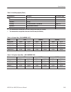
Period jitter Measured by TDS694C-1MHD with TDSJIT1
Typical Refer to Table 1-9.
Cycle to cycle jitter Measured by TDS694C-1MHD with TDSJIT1
Typical Refer to Table 1-10.
Marker skew
4
32 ps
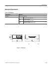
Connector Rear panel SMB connectors
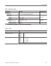
Offset
Clock out
5
Page 4-76
Level ECL 100 K compatible (internally loaded in 50 W to -2 V and 43 W
series terminated)
Period jitter Measured by TDS694C-1MHD with TDSJIT1
Typical Refer to Table 1-11.
Cycle to cycle jitter Measured by TDS694C-1MHD with TDSJIT1
Typical Refer to Table 1-12.
Connector Rear panel BNC connectors