


Removal and Installation Procedures
6-32
AWG510 & AWG520 Service Manual
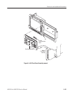
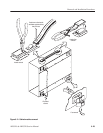
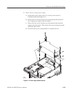
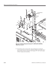
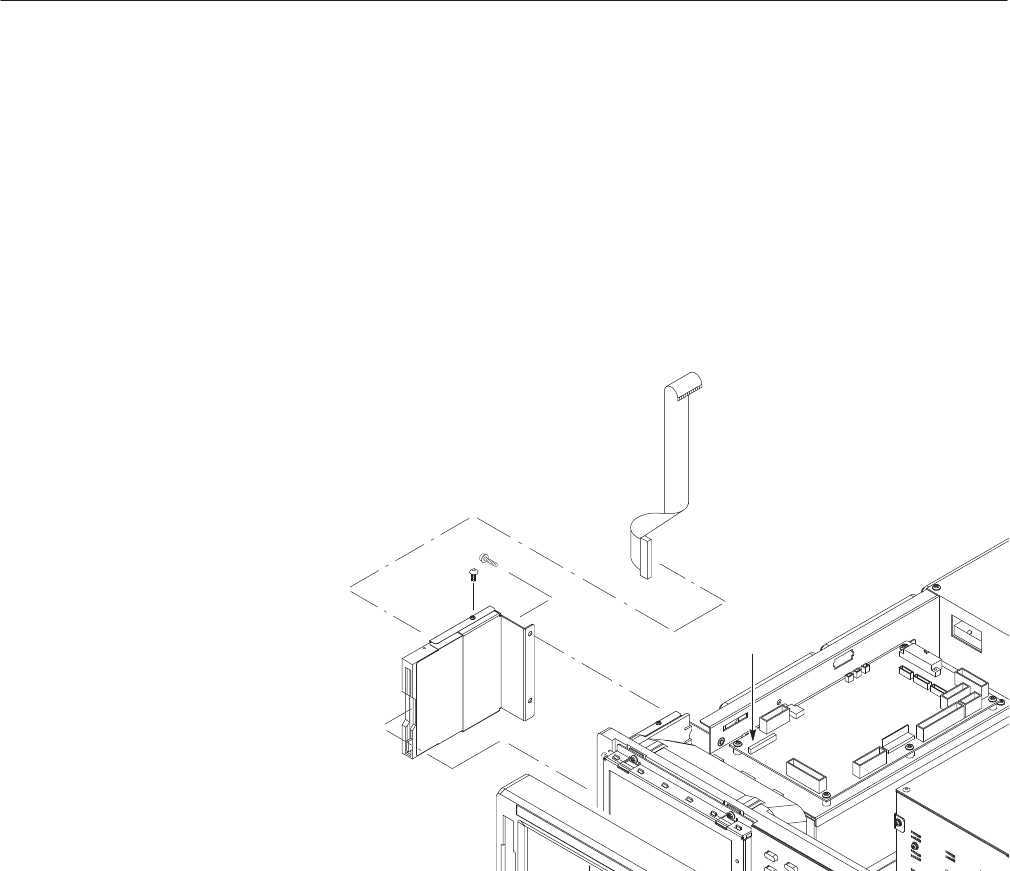
3. Remove the Floppy Disk Drive: Use Figure 6–13 as a guide.
a. Unplug the J124 floppy driver connector (ribbon interconnect cable) that
connects the disk drive to the A10/A11 Connector board.
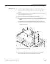
b. Use the screwdriver with Phillips #2 tip to remove the two screws
securing the floppy disk bracket to the main chassis, and lift it away
from the chassis. When removing the disk drive main body, use the
screwdriver with Phillips #1 tip to remove the two screws securing the
drive to the bracket, then pull out the disk drive.
J124
Figure 6-13: Floppy Disk removal
4. Reinstallation: Do, in reverse order, substeps 3b then 3a to reinstall the
floppy disk drive. Then refer to the procedure Cabinet (page 6–20) to
complete reassembly of the generator:
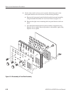
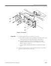
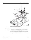
1. Assemble equipment and locate module to be removed: Have handy a
screwdriver with a size Phillips #2 tip (Items 1 and 3). Locate the fan in the
locator diagram Outer-Chassis Modules, Figure 6–3, page 6–14.
2. Orient the waveform generator: Set the generator so its bottom is down on
the work surface and its right side is facing you.
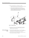
PS100 Low Voltage Power
Supply