


Performance Verification
4-34
AWG510 & AWG520 Service Manual
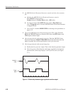
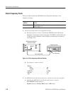
H Check that the positive minus negative voltages fall within
200 mV ± 5 mV.
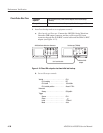
e. Enter numeric value of 2: Push 2 and ENTER keys in this order to set
the amplitude to 2 V.
f. Check the amplitude accuracy of 2 V amplitude setting:
H Push the FORCE EVENT button.
H Write the reading on DMM as a positive voltage.
H Push the FORCE EVENT button.
H Write the reading on DMM as a negative voltage.
H Check that the positive minus negative voltages fall within
2 V ± 0.032 V.
5. Check CH1
or CH2: Repeat the Check Amplitude Accuracy for the AWG510
CH1
or the AWG520 CH2, depending on the instrument that you are
currently testing.
6. End procedure: Retain the test hookup and control settings.
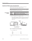
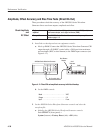
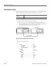
1. Use the test hookup and settings from previous check.
2. Set AWG500–Series Waveform Generator controls and select the sequence
file:
a. Initialize the AWG500–Series Waveform Generator controls: Push
UTILITY (front–panel)!
System (bottom)!Factory Reset (side)!OK (side).
b. Select the sequence file: Load the OFFSET.WFM as referring to the
procedures on page 4–15.
c. Push VERTICAL MENU (front–panel)!Amplitude (side).
d. Set the AWG500–Series Waveform Generator amplitude: Push 0, ., 0, 2
and ENTER keys in this order to set the amplitude to 0.020 V.
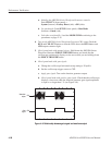
3. Turn on the AWG500–Series Waveform Generator CH1 output: Push the
RUN and CH1 buttons so that the LEDs above the RUN button and CH1
output connector light.
Check Offset Accuracy