


Performance Verification
4-74
AWG510 & AWG520 Service Manual
D1 connector. Proceed this step as changing the cable connection
from D1 to D9
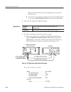
H Check the low level, high level and period: Do the procedures in step
4.a for each of DIGITAL DATA OUT connectors from D1 to D9.
5. End procedure: Retain the AWG520 settings.
Equipment
required
Two 50ĂΩ SMBĆtoĆBNC coaxial cables (same length), and
an oscilloscope.
Prerequisites The instrument must meet the prerequisites listed on page 4-13.
1. Install the test hookup and set test equipment controls:
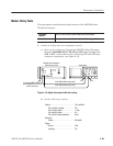
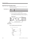
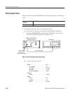
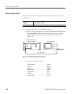
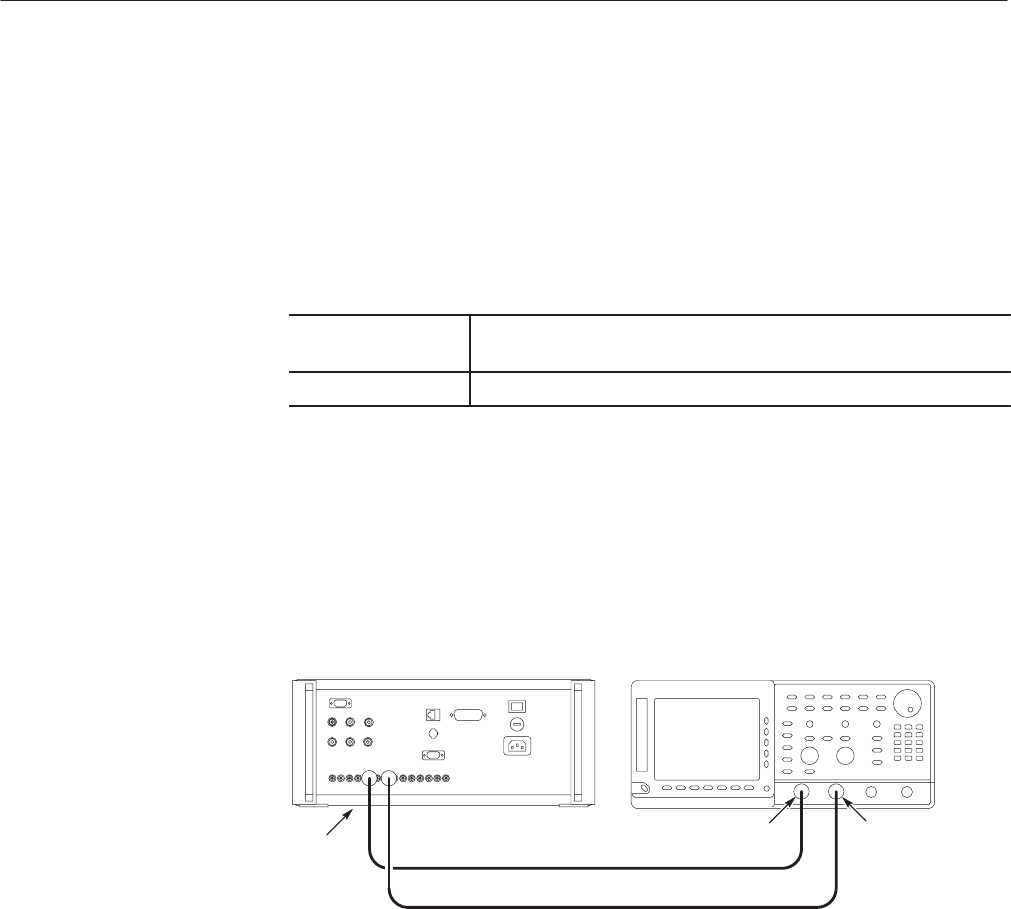
a. Hook up the oscilloscope: Connect the AWG500–Series Waveform
Generator DIGITAL DATA OUT:D0 and D1 outputs through 50 Ω
SMB-to-BNC coaxial cables with the same length to the oscilloscope
CH1 and CH2 input connectors, respectively (see Figure 4–35).
Oscilloscope
AWG500 Series Waveform
Generator rear panel
Connect the SMB connectors
end to DIGITAL DATA
OUT:D0 and D1 connectors
CH1 CH2
50 W SMBĆtoĆBNC coaxial cable
50 W SMBĆtoĆBNC coaxial cable
Figure 4-35: Digital data output initial test hookup
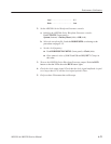
b. Set the oscilloscope controls:
Vertical . ........................ CH1andCH2
CH1 and CH2 coupling . ........ DC
CH1 and CH2 scale . ........... 1V/div
CH1 and CH2 offset . .......... 0V
CH1 and Ch2 input impedance . . . . 50 W
Horizontal
Sweep . .................... 0.5ms/div
Check Skew