


Specifications
1-12
AWG510 & AWG520 Service Manual
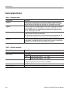
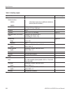
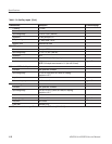
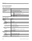
Table 1-14: Auxiliary inputs (Cont.)
Characteristics PV reference pageDescription
Threshold TTL level
Pulse width Minimum 64 clocks
Input voltage range 0 V to +5 V (DC + peak AC)
Impedance 2.2 kW, pullĆup to +5 V
Delay to analog out
x 462.5 clocks + 45 ns
Recovery Time Miaximum 500 clock
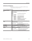
CH1 ADD input
Connector Rear panel BNC connector
Input voltage range -1 V to +1 V (DC + peak AC)
Impedance 50 W
Bandwidth DC to 200 MHz (-3 dB), 1 VpĆp input
Amplitude accuracy
"5%
NOTE: CH1 output cannot exceed "2 V (into a 50 W load).
Page 4-63
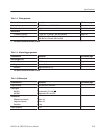
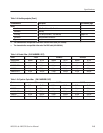
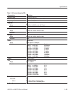
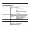
Reference 10 MHz clock input
Connector Rear panel BNC connector
Input voltage range 0.2 V to 3.0 VpĆp (into a 50 W load, AC coupling)
Maximum "10 V
Impedance 50 W
Reference frequency
10 MHz "0.1 MHz
Page 4-59
External clock input
Connector Rear panel BNC connector
Input voltage range 0.25 V
pĆp
to 1.0 V
pĆp
(into a 50 W load, AC coupling)
Maximum "10 V
Impedance 50 W
Frequency range 10 MHz to 1 GHz Page 4-61
Duty ration 40% to 60%
Pulse width Minimum 0.5 ns
7
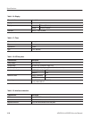
The characteristics are specified at the end of the BNC cable (012Ć0482Ć00).