


Performance Verification
4-78
AWG510 & AWG520 Service Manual
Noise Output Tests
This procedure checks the AWG500–Series Waveform Generator noise output
characteristics.
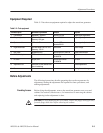
Equipment
required
A 50ĂΩ coaxial cable, a DC block, an adapter (N male to BNC female),
and a spectrum analyzer.
Prerequisites The instrument must meet the prerequisites listed on page 4-13.
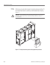
1. Install test hookup and set test equipment controls:
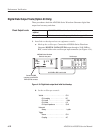
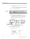
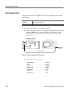
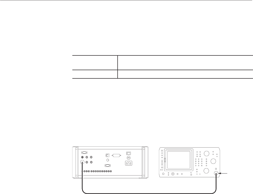
a. Hook up the spectrum analyzer: Connect the AWG500–Series Waveform
Generator NOISE OUT connector through the coaxial cable, adapter,
and DC Block to the input connector on the spectrum analyzer (see
Figure 4–37).
AWG500 Series Waveform
Generator rear panel
Spectrum Analyzer
50 W coaxial cable
Adapter and
DC Block
Figure 4-37: Noise output initial test hookup
b. Set spectrum analyzer controls:
Centerfrequency ................. 100MHz
Full span . ...................... 500MHz
Vertical . ........................ 10dB/div
Referencelevel................... 0dB/div
RF attenuation . .................. 20dB
Video filter . ..................... 10kHz
Resolution BW . .................. 1MHz