


Specifications
AWG510 & AWG520 Service Manual
1-11
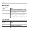
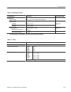
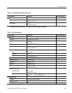
Table 1-13: Digital data out (option 03) (Cont.)
Characteristics
6
PV reference pageDescription
Delay
Data to marker 4.4 ns
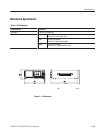
See Figure 1-2 for T
d5
.
Clock to data 3.7 ns
See Figure 1-2 for T
d6
.
6
The characteristics are specified at the end of the SMB-BNC cable (012Ć1459Ć00).
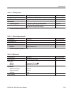
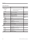
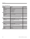
Table 1-14: Auxiliary inputs
Characteristics Description PV reference page
Trigger input
7
Connector Rear panel BNC connectors
Impedance
50 W "2 W
1kW "100 W
Polarity POS (positive) or NEG (negative)
Input voltage range
"10V,intoa1kW load
"5V,intoa50W load
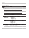
Threshold
Level -5.0 V to 5.0 V
Resolution 0.1 V
* Accuracy
"(5 % of level + 0.1 V)
Page ****
Pulse width Minimum 10 ns, 0.2 V amplitude
Trigger dead time Maximum 500 ns
Trigger jitter Maximum 1.6 ns
Gate jitter Maximum 32 clocks
Delay to marker, Typical 30 ns + 1 clock
See Figure 1-2 for T
d2
Delay to data, Typical
TRIGGER mode 37 ns + 1 clock
See Figure 1-2 for T
d1
.
GATE mode Minimum 45 ns + 358.5 clocks
Miaximum 45 ns + 430.5 clocksĂ
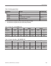
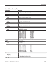
Event trigger input
Connector 9Ćpin, D type on the rear panel
Number of events 4 bits
Input signal 4 event bits and Strobe