


AWG510 & AWG520 Service Manual
6-55
Troubleshooting
This subsection contains information and procedures designed to help you isolate
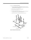
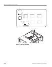
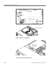
faulty modules in the waveform generator. If a module needs to be replaced,
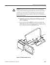
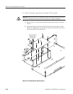
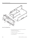
follow the Removal and Installation Procedures located in this section.
This subsection consists of the following flowcharts:
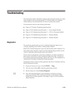
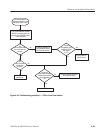
H Figure 6–27: Primary Troubleshooting Procedure
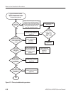
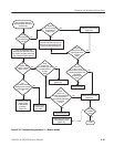
H Figure 6–28: Troubleshooting Procedure 1 — Power Supply Module
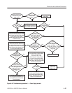
H Figure 6–30: Troubleshooting Procedure 2 — CPU or Front-panel Module
H Figure 6–32: Troubleshooting Procedure 3 — Monitor Module
H Figure 6–37: Troubleshooting Procedure 4 — Module Isolation
Diagnostics
The waveform generator has two levels of internal diagnostics that focus on
verifying, adjusting, and if need be, isolating faulty modules.
Both levels of internal diagnostics report any bad modules and/or interfaces. If a
bad module and/or interface is found, use the troubleshooting procedures in this
section to determine which module needs to be replaced.
The two levels of diagnostics are the short confidence set and the extended set
that tests the oscilloscope circuitry in depth and takes more time. At power on,
the waveform generator automatically executes the short set. The extended set is
optional and is executed by using the following procedure:
Prerequisites: Power on the waveform generator and allow a 20 minute warm-up
before doing this procedure.
1. Display the diagnostics menu: Press UTILITY ! Diag.
2. Select the menu: Select ALL using the general purpose knob.
3. Run the diagnostics: Press Execute Diagnostic.
4. Wait: The internal diagnostics do an exhaustive verification of proper
oscilloscope function. This verification will take several minutes. When
finished, the waveform generator will display a report of any bad modules
and/or interfaces.