


Removal and Installation Procedures
AWG510 & AWG520 Service Manual
6-37
1. Assemble equipment and locate modules to be removed: Have handy a
screwdriver with a size Phillips #2
tip (Items 1 and 3). Find the modules to
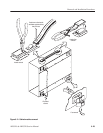
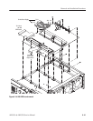
be removed in the locator diagram Outer-Chassis Modules, Figure 6–3,
page 6–14.
2. Orient the waveform generator: Set the generator so its top is down on the
work surface and its front is facing you.
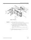
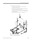
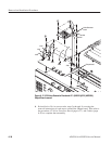
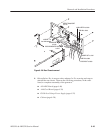
3. Remove the A75 Noise Generator Board: Use Figure 6–17 as a guide.
a. Disconnect two coax cables at J197 and J198.
b. Remove the five screws attaching the A75 Noise Generator board to the
A71/A72 Output board.
c. Disconnect the Noise Generator board from the Output board, then lift it
up away to complete removal.
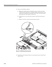
4. Reinstallation: Do, in reverse order, steps 3a through 3c reversing the
removal instructions of each step to reinstall the Noise Generator board.
1. Assemble equipment and locate modules to be removed:
a. Have handy a screwdriver with a size Phillips #2
tip (Items 1 and 3).
b. Locate the modules to be removed in the locator diagram Outer-Chassis
Modules, Figure 6–3, page 6–14.
c. Do the procedure A75 Noise Generator Board that precedes this
procedure to remove the interconnect cables.
2. Orient the waveform generator: Set the generator so its top is down on the
work surface and its front is facing you.
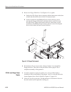
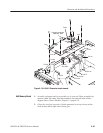
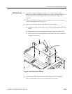
3. Remove A71 (AWG510)/A72 (AWG520)
Output Board: Use Figure 6–17 as a guide.
a. Unplug these cables and connector:
H The coax cables from ADD INPUT at J300, NOISE IN at J310,
CH 1 OUTPUT at J195, and CH 2 (AWG520)/CH 1 INVERT
(AWG520) OUTPUT at J295.
H The interconnect cables from the A50 AWG board at J100, J102,
J200, and J202.
H The cable connector from the A50 AWG board at J700.
b. Remove the four screws attaching the Output board to the main chassis.
c. Lift the Output board up away from the main chassis to complete the
removal.
A75 Noise Generator
Board
A71 AWG510)/
A72 (AWG520)
Output Board