


Performance Verification
AWG510 & AWG520 Service Manual
4-23
Operating Mode Tests
These procedures check operation of the Cont, Triggered and Gated modes.
Equipment
required
A 50ĂΩ coaxial cable and an oscilloscope.
Prerequisites The AWG500-Series Waveform Generator must meet the prerequisites
listed on page 4-13.
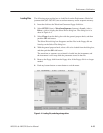
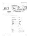
1. Install the test hookup and set test equipment controls:
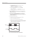
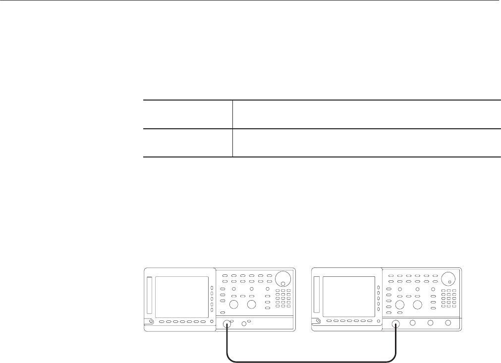
a. Hook up the oscilloscope: Connect the AWG500–Series Waveform
Generator CH1 output connector through the coaxial cable to the
oscilloscope CH1 input connector (see Figure 4–5).
Oscilloscope
50 W coaxial cable
AWG500 Series Waveform Generator
Figure 4-5: Cont mode initial test hookup
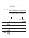
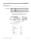
b. Set the oscilloscope controls:
Vertical . ........................ CH1
CH1 coupling . ............... DC
CH1 scale . ................. 0.2V/div
CH1 input impedance . ......... 50W
Horizontal
Sweep . .................... 500ns/div
Trigger
Source . .................... CH1
Coupling .................... DC
Slope ...................... Positive
Level ...................... +100 mV
Mode . ..................... Auto
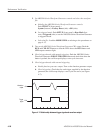
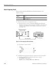
Check Cont Mode