


Performance Verification
4-62
AWG510 & AWG520 Service Manual
Horizontal
Sweep . .................... 500ns/div
Trigger
Source ..................... CH1
Coupling .................... DC
Slope...................... Positive
Level ...................... +100 mV
Mode ...................... Auto
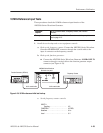
d. Set the signal generator controls:
Mode .......................... Continuous
Parameters ......................
Frequency .................. 1GHz
Amplitude . .................. 0.25 V
p-p
Output . ........................ On
2. Set the AWG500–Series Waveform Generator controls and select the
waveform file:
a. Initialize the AWG500–Series Waveform Generator controls:
Push UTILITY (front–panel)!
System (bottom)!Factory Reset (side)!OK (side).
b. Select the file: Load the MODE.WFM as referring to the procedures on
page 4–15.
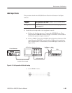
c. Set the AWG500–Series Waveform Generator clock source to external:
Push HORIZONTAL MENU (front–panel)!Clock Src (side) so that
the clock reference is set to External.
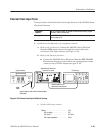
3. Turn on the AWG500–Series Waveform Generator CH1 output: Push the
RUN and CH1 OUT buttons so that the LEDs above the RUN button and
CH1 output connector light.
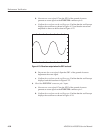
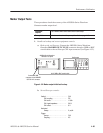
4. Check against limits: Check that the amplitude of the sine wave displayed on
the oscilloscope is 5 vertical divisions and that the waveform of one cycle
per 2 horizontal divisions is displayed.
5. End procedure: Turn the signal generator output off and disconnect the
signal generator .