


Performance Verification
AWG510 & AWG520 Service Manual
4-53
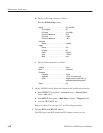
Tr igger
Source . .................... CH1
Coupling .................... DC
Slope ...................... Positive
Level ...................... +100 mV
Mode . ..................... Auto
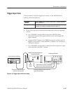
2. Set all the switches of the ground closure to open.
3. Set the AWG500–Series Waveform Generator controls and select the
sequence file:
a. Initialize the AWG500–Series Waveform Generator controls:
Push UTILITY (front–panel)!
System (bottom)!Factory Reset (side)!OK (side).
b. Select the sequence file: Load the PT_EVENT.SEQ as referring to the
procedures on page 4–15.
c. Set the AWG500–Series Waveform Generator to enhanced mode: Push
SETUP (front–panel)!Run Mode (bottom)!Enhanced (side) to set
the enhanced mode.
4. Turn on the AWG500–Series Waveform Generator CH1 output: Push the
RUN and CH1 OUT buttons so that the LEDs above the RUN button and
CH1 output connector light.
5. Check the EVENT IN connector pin 0 input:
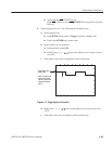
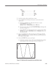
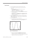
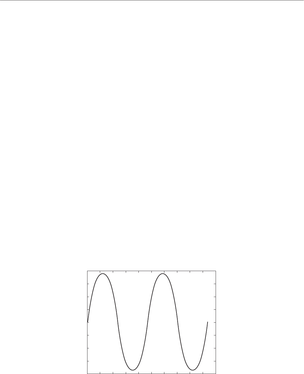
a. Confirm the waveform on the oscilloscope: Confirm that the waveform
being displayed on the oscilloscope is as shown in Figure 4–22.
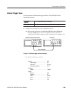
Figure 4-22: Waveform while all ground disclosure switches are open