


Removal and Installation Procedures
6-58
AWG510 & AWG520 Service Manual
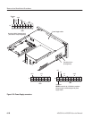
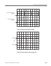
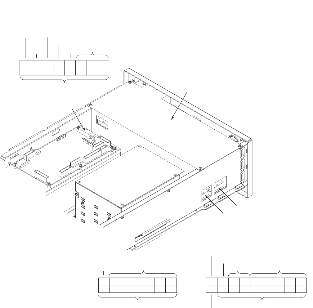
9 10 11 12 13 14 15 16
132 45678
+5 V
GND
+12 V
+24 V
-4.6 V
*Power
Fail
*Remote
On
-4.6 V
GND
123456789
101112131415161718
-2 V
*15V/8Vsel
-8 V
+8 V
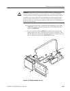
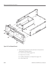
J3 on the A10/A11 Connector board
(See above for the pin assignment)
NEVER connect the pin *15V/8Vsel to anywhere.
Always be open to avoid damage to the power
supply module.
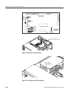
J1
J2
J3
14 13 12 11 10 9 8
756 4321
+5 V
GND
J1
J2
+12 V
(See below for the
pin assignment)
Power Supply module
Figure 6-29: Power Supply connectors