


Removal and Installation Procedures
6-24
AWG510 & AWG520 Service Manual
4. Remove the trim ring: Grasp the trim ring by its top edge and pry it up and
lift it forward to snap it off of the front subpanel. If servicing the menu
buttons, lift them out of the trim ring. (When reinstalling, reinsert the menu
buttons, align the trim ring to the front subpanel and press it back on.)
5. Remove the output panel: Gently pry, using your fingers, the snap-off/snap-
on output panel away from the front subpanel to remove it. (When reinstal-
ling, use your hands to press it back on.)
6. Reinstallation: Do in reverse steps 3–5 to reinstall the output panel, menu
buttons, and trim ring, following the reinstallation instructions found in each
step.
NOTE. This procedure includes removal and reinstallation instructions for the
front panel and front panel buttons. Unless either of those modules are being
serviced, do not do step 4, “Further disassembly of front-panel assembly.”
1. Assemble equipment and locate modules to be removed:
a. Have handy a screwdriver with a size Phillips #2
tip (Items 1 and 3).
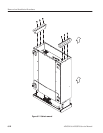
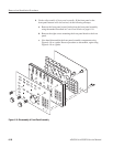
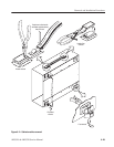
b. Locate the modules to be removed in the locator diagram External
modules, Figure 6–2.
c. Do the procedure Trim Ring, Menu Buttons, and Output Panel, steps
1–5, immediately preceding this procedure.
2. Orient the waveform generator: Set the generator so its bottom is down on
the work surface and its front is facing you.
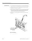
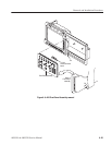
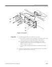
3. Remove the front-panel assembly:
a. Lift the front-panel assembly out of the front subpanel until you can
reach the interconnect cable connecting it to the Connector board.
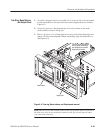
b. Disconnect that cable at J121 of the Connector board. Disconnect the
flex-board connector at P3 of the front-panel assembly. (The flex board
is part of the display-frame assembly). See Figure 6–9.
c. Finally, lift the front-panel assembly out of the front subpanel to
complete the removal.
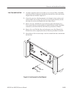
A20 FrontĆPanel Assembly