


Performance Verification
4-16
AWG510 & AWG520 Service Manual
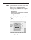
NOTE. The floppy disk file list displayed on the screen does not automatically
update when you replace the diskette with another one. To update the file list,
re-select the floppy disk drive.
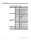
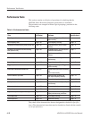
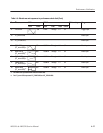
Table 4–6 lists the sequence and waveform files on the Performance Check/Ad-
justment disk (063-2983-XX) that are used in these performance tests, the
AWG500–Series Waveform Generator front-panel settings that each file sets up,
and the performance test that uses each file.
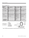
NOTE. The files on the Performance Check disk are locked (the files are marked
by the icon
in the file list), so the data in these files cannot be changed
unless the lock is opened.
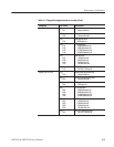
Table 4-6: Waveforms and sequences in performance check disk
No. File name EDIT menu SETUP menu Marker setup Usage
Form Points Clock Filter Ampl Offset
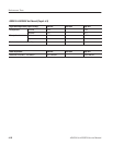
1 MODE.WFM 1000 1 GHz Through 1ĂV 0ĂV Marker1,2:
0 to 499: High,
500 to 999: Low
Run mode,Trigger
level, Marker
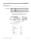
2 PULSE.WFM 1000 100 MHz Through 1ĂV 0ĂV Pulse amplitude, InĆ
ternal trigger accuracy
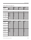
3 SINE.WFM 256 1 GHz Through 1ĂV 0ĂV Sine characteristics
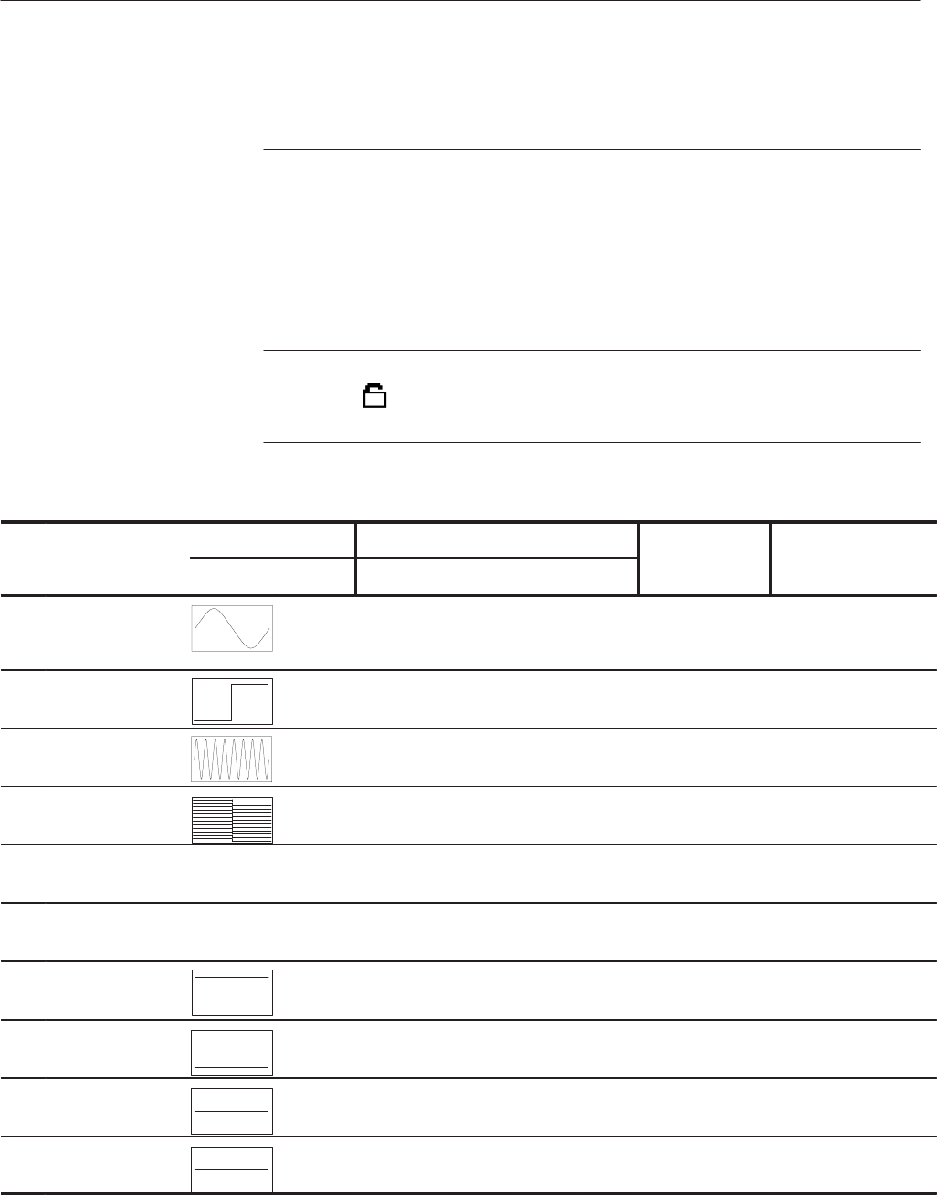
4 DOUT.PAT 512 100 MHz Through 1ĂV 0ĂV Digital data out
5 AMP1.SEQ Amplitude accuracy
(Normal out)
6 AMP2.SEQ Amplitude accuracy
(Direct out)
7 DC_P.WFM
(AMPx.SEQ)
1
1000 100 MHz Through 1ĂV 0ĂV Amplitude accuracy
8 DC_M.WFM
(AMPx.SEQ)
1
1000 100 MHz Through 1ĂV 0ĂV Amplitude accuracy
9 DC0.WFM
(AMP2.SEQ)
1000 100 MHz Through 1ĂV 0ĂV Amplitude accuracy
10 OFFSET.WFM 1000 100 MHz Through 20 mV 0ĂV Offset accuracy
Performance
Check/Adjustment Files