


Performance Verification
AWG510 & AWG520 Service Manual
4-65
Marker Output Tests
These procedures check the accuracy of the AWG500–Series Waveform
Generator marker output level.
Equipment
required
A 50ĂΩ SMBĆtoĆBNC coaxial cable and an oscilloscope.
Prerequisites The instrument must meet the prerequisites listed on page 4-13.
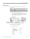
1. Install test hookup and set test equipment controls:
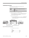
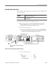
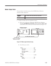
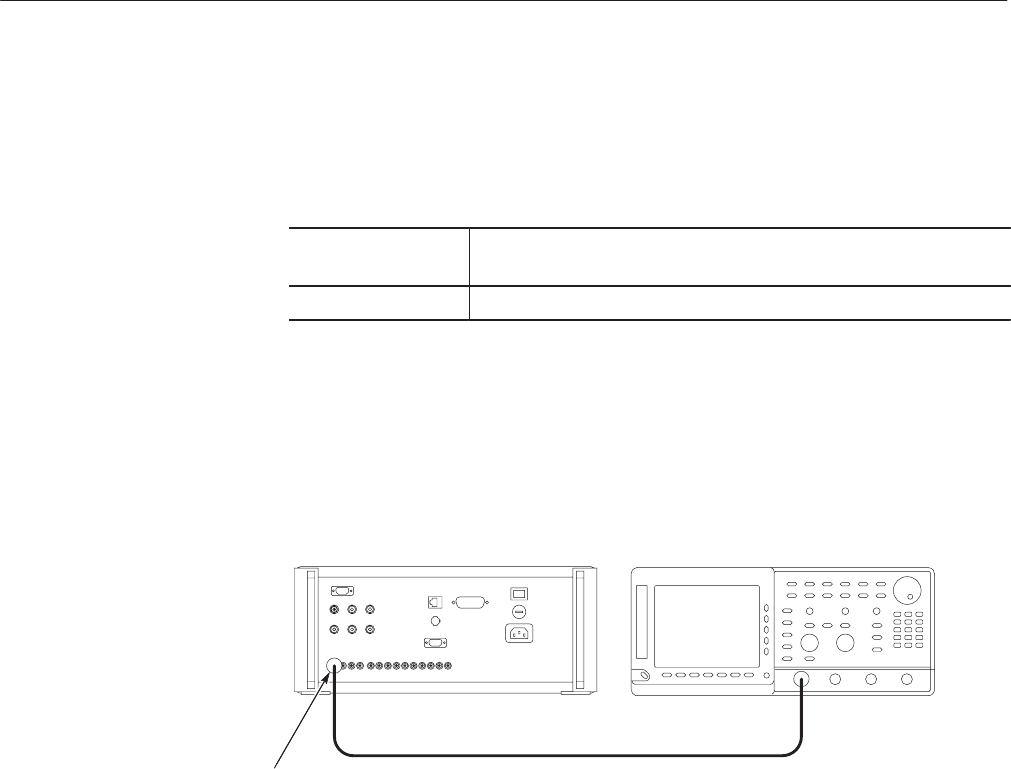
a. Hook up the oscilloscope: Connect the AWG500–Series Waveform
Generator MARKER OUT:CH1 M1 connector through a SMB-to-BNC
coaxial cable to the oscilloscope CH1 input connector (see Figure 4–32).
Oscilloscope
AWG500 Series Waveform
Generator rear panel
50 W SMBĆtoĆBNC coaxial cable
Connect the SMB
connector end to MARKER
OUT:CH1 M1 connector
Figure 4-32: Marker output initial test hookup
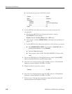
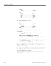
b. Set oscilloscope controls:
Vertical . ........................ CH1
CH1 coupling . ............... DC
CH1 scale . ................. 1V/div
CH1 input impedance . ......... 50W
CH1 offset . ................. 0V
Horizontal
Sweep . .................... 2ms/div
Trigger
Source . .................... CH1
Coupling .................... AC