


Removal and Installation Procedures
6-40
AWG510 & AWG520 Service Manual
1. Assemble equipment and locate modules to be removed:
a. Have handy a screwdriver with a size Phillips #2 tip (Items 1 and 3).
b. Locate the modules to be removed in the locator diagram Outer-Chassis
Modules, Figure 6–3, page 6–14.
c. Do the procedure A71 (AWG510)/A72 (AWG520)
Output Board that precedes this procedure to remove the Output board.
2. Orient the waveform generator: Set the generator so its left side is down on
the work surface and its rear is facing you.
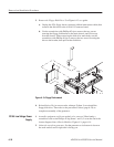
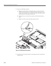
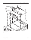
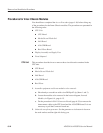
3. Remove the A50 AWG Board.: Use Figure 6–19 as a guide while doing the
following substeps.
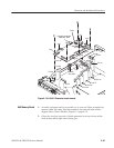
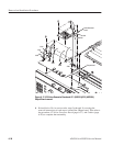
a. Unplug these cables and connectors:
H Two connectors J1 and J2 on the low–voltage power supply.
H The cable from EVENT INPUT at J200 on the AWG Board.
H The coax cable to CLOCK OUTPUT at J500 on the AWG Board.
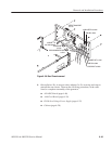
H The interconnect cable from J130 on the A30 GPIB board to J100 on
the AWG board at the cable junction. See also Figure 6–21, page
6–45.
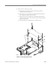
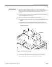
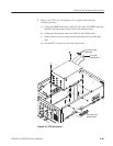
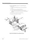
b. Remove the twelve screws on top of the AWG board and two from the
rear panel.
c. Lift the AWG board up away from the main chassis to complete the
removal.
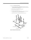
4. Reinstallation: Do, in reverse order, substeps 3b then 3a reversing each step
to reinstall the board. Then refer to the following procedures, in order listed,
to complete the reassembly.
H A71 (AWG510)/A72 (AWG520)
Output Board
H Cabinet (page 6–20).
A50 AWG Board