


Performance Verification
AWG510 & AWG520 Service Manual
4-51
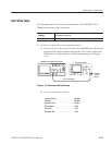
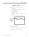
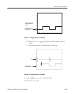
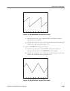
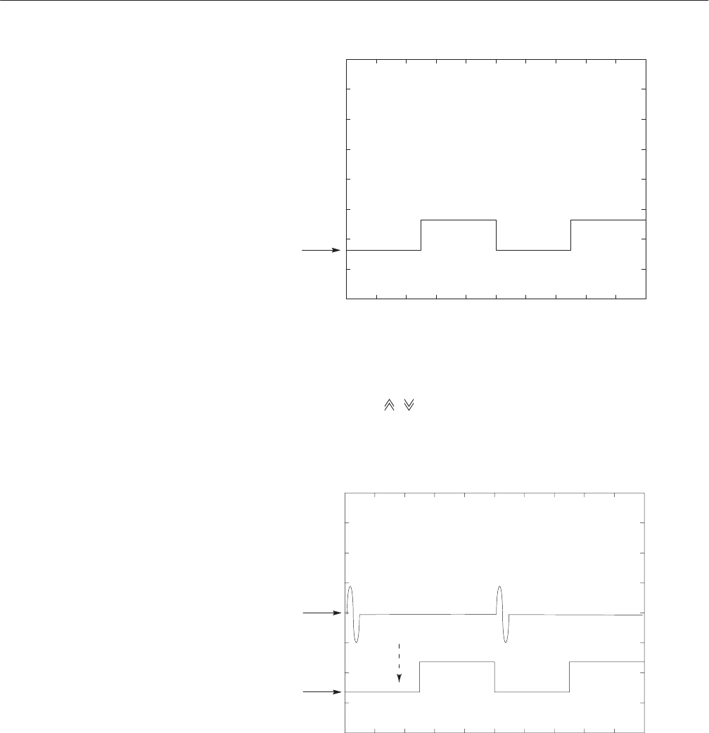
Trigger Signal CH2
(-4.65 V level)
NOTE: In step 5b this
voltage level equals
-4.65 V.
Figure 4-19: Trigger Signal (-5V check1)
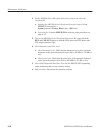
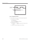
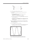
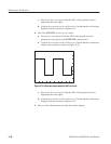
d. Push Cursor, %, &,
, keys as the low level of a pulse to be set to
–5.35V.
e. Verify that a sine wave is displayed on the oscilloscope.
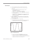
Trigger Signal CH2
(-5.35 V level)
CH1
Figure 4-20: Trigger Signal (-5V check2)
6. Push the RUN button to turn off the RUN LED.
7. Disconnect all the cable.