


Performance Verification
AWG510 & AWG520 Service Manual
4-41
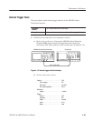
2. Set the AWG500–Series Waveform Generator controls and select the
waveform file:
a. Initialize the AWG500–Series Waveform Generator controls:
Push UTILITY (front–panel)!
System (bottom)!Factory Reset (side)!OK (side).
b. Select the file: Load the PULSE.WFM as referring to the procedures on
page 4–15.
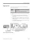
3. Turn on the AWG500–Series Waveform Generator CH1 output: Push the
RUN and CH1 OUT buttons so that the LEDs above the RUN button and
CH1 output connector light.
4. Check pulse response at 1 V amplitude:
a. Check rise time: Check that the rise time of the waveform displayed on
the oscilloscope from 10% to 90% point is equal to or less than 1.5 ns.
b. Check aberration:
H Set oscilloscope sweep to 12.5 ns/div (or 20 ns/div).
H Check that the aberration of the displayed waveform on the
oscilloscope screen is within ± 7 %.
c. Check flatness:
H Set oscilloscope sweep to 200 ns/div.
H Check that the flatness of the displayed waveform on the oscillo-
scope is within ± 3 % after 50 ns from the rising edge.
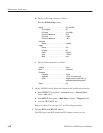
5. Check pulse response at 2 V amplitude:
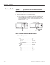
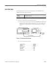
a. Change the oscilloscope controls:
Vertical . ........................ CH1
CH1 scale . ................. 0.5V/div
b. Change the AWG500–Series Waveform Generator controls:
H Push VERTICAL MENU!Amplitude.
H Enter numeric value of 2: Push 2 and ENTER keys in this order.