Performance Verification
AWG510 & AWG520 Service Manual
4-67
NOTE. At the marker level measurements from an oscilloscope, do not measure
the high and low level voltages that contain the ringing by overshoot or
undershoot. Always perform the measurements after the level has been stabled.
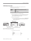
4. Check CH1 marker output level accuracy:
a. Check Marker 1 output level:
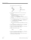
H Check that the reading for the low level on the oscilloscope screen is
within the range between –2.2 V and –1.8 V.
H Check Marker 1 output high level: Check that the reading for the
high level on the oscilloscope screen is in the range between
1.8 V and 2.2 V.
b. Change the hook up: Disconnect the SMB-to-BNC cable from the
AWG500–Series Waveform Generator MARKER OUT:CH1 M1
connector and connect it to the MARKER OUT:CH1 M2 connector
c. Check Marker 2 output level:
H Check that the reading for the low level on the oscilloscope screen is
within the range between –2.2 V and –1.8 V.
H Check Marker 1 output high level: Check that the reading for the
high level on the oscilloscope screen is within the range between
1.8 V and 2.2 V.
5. Check CH2 marker output level accuracy (for the AWG520 only):
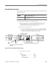
a. Change the hook up: Disconnect the SMB-to-BNC cable from the
AWG500–Series Waveform Generator MARKER OUT:CH1 M2
connector and connect it to the MARKER OUT:CH2 M1 connector
b. Check Marker 1 output level:
H Check Marker 1 output low level: Check that the reading for the low
level on the oscilloscope screen is within the range between –2.2 V
and –1.8 V.
H Check Marker 1 output high level: Check that the reading for the
high level on the oscilloscope screen is within the range between
1.8 V and 2.2 V.
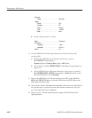
c. Change the hook up: Disconnect the SMB-to-BNC cable from the
AWG500–Series Waveform Generator MARKER OUT:CH2 M1
connector and connect it to the MARKER OUT:CH2 M2 connector
d. Check Marker 2 output level:


