


Removal and Installation Procedures
AWG510 & AWG520 Service Manual
6-35
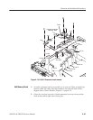
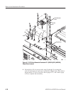
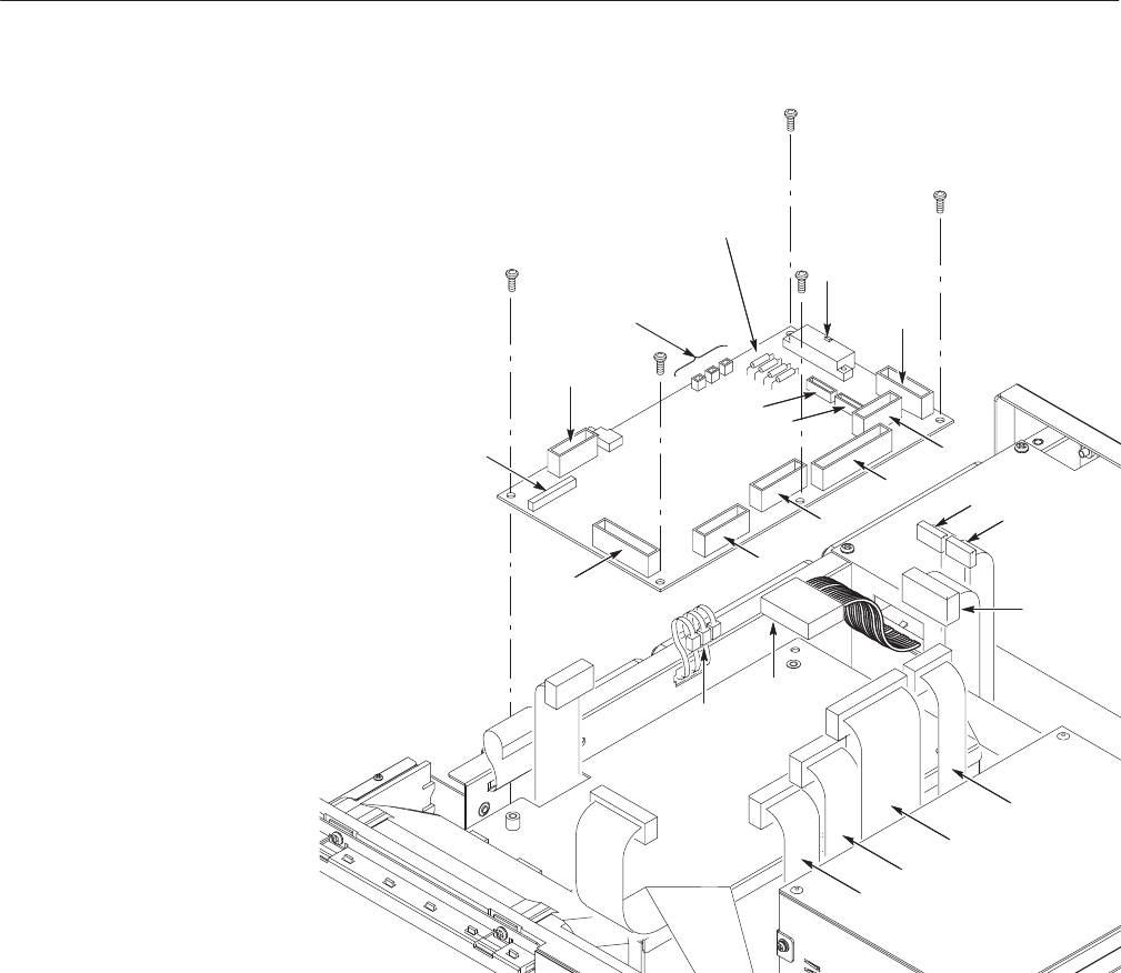
J125
J3
J110
J113
J122
J115
J121
J124
Fan power connectors
J930, J931, J932
J112
J127
J128
To J124
To J125
To J121
To J115
To J122
To J113
To J112
To J910,
J911, J912
To J110
To J3
To J128
To J127
Fuses
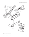
Figure 6-15: A10/A11 Connector board removal
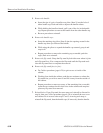
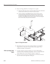
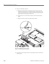
1. Assemble equipment and locate modules to be removed: Have an angled–tip
tweezers (Item 10) handy. Find the modules to be removed in the locator
diagram Outer-Chassis Modules, Figure 6–3, page 6–14.
2. Orient the waveform generator: Set the generator so its top is down on the
work surface and its right side is facing you.
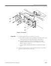
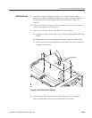
A60 Memory Board