


Removal and Installation Procedures
AWG510 & AWG520 Service Manual
6-17
5. If the module is an inner-chassis module, access the inner-chassis:
a. If removing the display tube, display-driver board, or the front subpanel,
first do the procedure Trim Ring, Menu Buttons, and Output Panel,
found under Procedures for External Modules. Also remove the
display-frame assembly found under Procedures for External Modules,
on page 6–17.
b. Also, if removing the front subpanel, do A20 Front-Panel Assembly also
found under Procedures for External Modules.
c. Do the procedure A10/A11 Connector Board found under Procedures for
Outer-Chassis Modules, page 6–30.
d. Find and do the procedure whose title matches the name of the module
to be removed under Procedures for Inner-Chassis Modules, page 6–44.
6. Reinstall all modules removed: Read the instructions found at the end of the
procedure that removes the module to be service. These instructions will
guide you in reinstalling all modules removed.
Procedures for External Modules
Do the Access Procedure (page 6–16) before doing any procedure in this
collection.
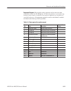
The following procedures are found here and are listed in order presented.
H Front-Panel Knobs
H Line Fuse and Line Cord
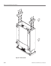
H EMI Gaskets
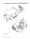
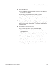
H Cabinet
H Trim Ring, Menu Buttons, and Output Panel
H A20 Front-Panel Assembly
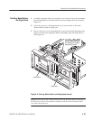
H Display Frame Assembly
H Cabinet Modules