


Removal and Installation Procedures
6-34
AWG510 & AWG520 Service Manual
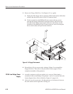
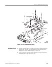
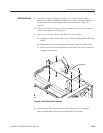
4. Reinstallation: Do, in reverse order, substeps 3a through 3d to reinstall the
low–voltage power supply. Then refer to the procedure Cabinet (page 6–20)
to complete reassembly of the generator:
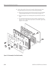
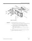
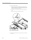
1. Assemble equipment and locate modules to be removed: Have handy a
screwdriver with a size Phillips #2 tip (Items 1 and 3). Find the modules to
be removed in the locator diagram Outer-Chassis Modules, Figure 6–3,
page 6–14.
2. Orient the waveform generator: Set the generator so its bottom is down on
the work surface and its front is facing you.
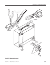
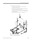
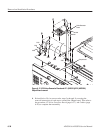
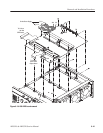
3. Remove the A10/A11 Connector Board:
a. Disconnect these cables and connectors. See Figure 6–15 as a guide.
H Three fan’s power cables at J930, J931, and J932.
H The cable from the low–voltage power supply at J3.
H The interconnect cables from CPU board at J110, J112, and J113.
H The interconnect cables to the Monitor Out at J127 and the A90 Key
board at J128.
H The interconnect cable from the A30 GPIB board at J115.
H The interconnect cable from the Back Plane at J122.
H The cables from the A20 Front Panel board at J121.
H J125 video signal connector and J124 floppy driver connector.
b. Using a screwdriver with a size Phillips #2 tip, remove the five screws
attaching the A10/A11 Connector board to the chassis.
c. Lift the board up and away from the chassis to complete the removal.
4. Reinstallation: Do, in reverse order, substeps 3a through 3c reversing each
step to reinstall the A10/A11 Connector board. Then refer to the procedure
Cabinet (page 6–20) to complete reassembly of the generator:
A10/A11 Connector Board