


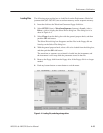
Performance Verification
4-10
AWG510 & AWG520 Service Manual
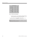
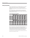
Finding Faulty Modules
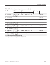
Table 4–2 shows the module test error code examples. The error code composes
of 54XX and 57XX, which corresponds to J7XX and J6XX modules and to
J12XX and J11XX, respectively. The lower two digits (XX) indicates the
possible faulty module, whose lower 6 bits correspond to the modules as shown
in Table 4–2.
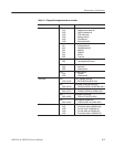
The 1 in the table indicates a possible faulty module. For example, the 1s are
placed in the J620 and J610 columns for the line of the error code 5406. The
lower two–digit 06 is driven from the binary bit array 000110, which means that
the J620 and/or J610 can be faulty.
Table 4-2: Module test error code examples
Possibly faulty modules
Error code J720 J710 J700 J620 J610 J600
5406 0 0 0 1 1 0
5407 0 0 0 1 1 1
5448 1 1 0 0 0 0
5456 1 1 1 0 0 0
Possibly faulty modules
Error code J1220 J1210 J1200 J1120 J1110 J1100
5706 0 0 0 1 1 0
5707 0 0 0 1 1 1
5748 1 1 0 0 0 0
5756 1 1 1 0 0 0
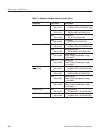
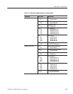
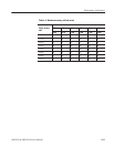
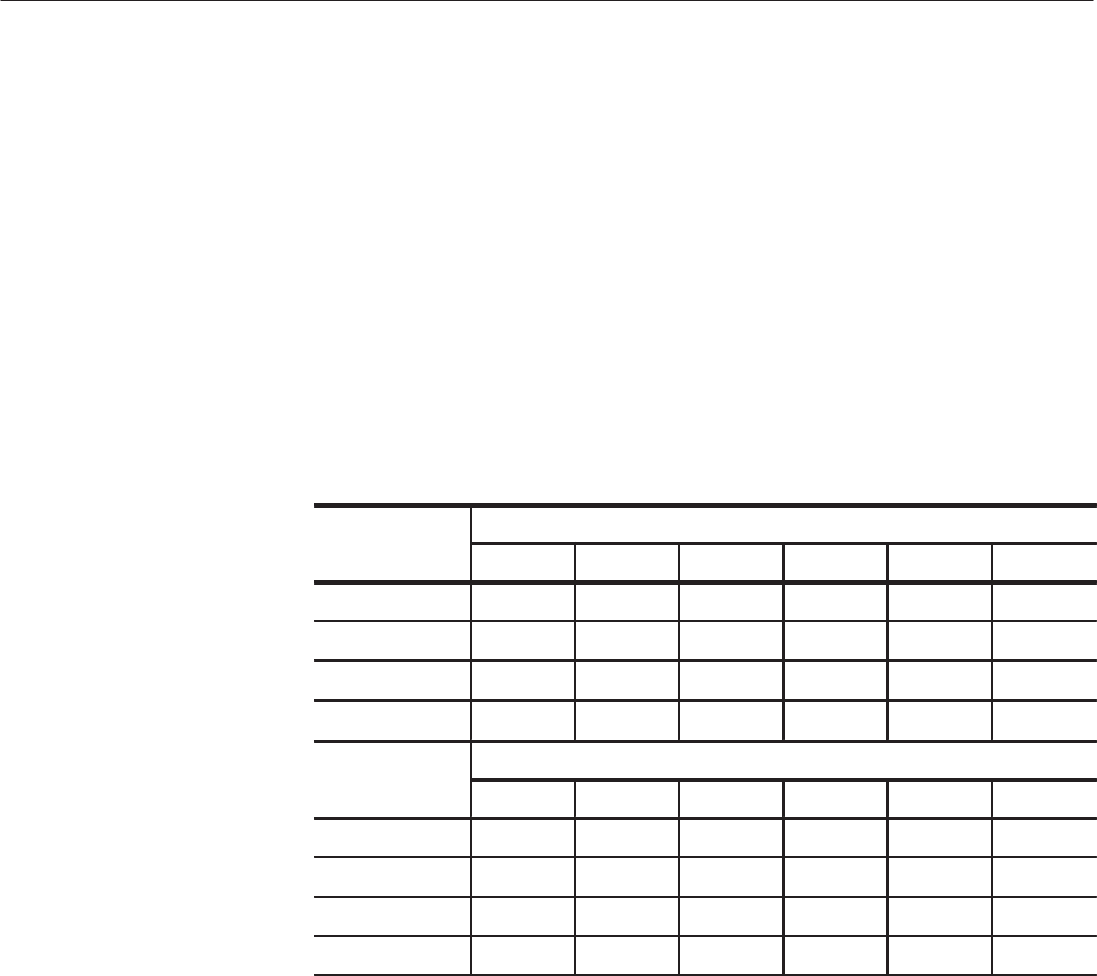
Table 4–3 shows the matrix of faulty modules and memory cells driven from the
lower two digits in the memory cell test error code. The J6XX and J7XX
modules correspond to the error code 55XX, and the J11XX and J12XX modules
correspond to the error code 58XX. If an error code is displayed, first you find a
lower two–digits in the table, and then find a faulty module included in the
corresponding column and a memory cell included in the corresponding line.
For example, if the error code 5827 is displayed, the J1200 module and/or U120
memory cell can be indicated as a faulty.