Performance Verification
4-24
AWG510 & AWG520 Service Manual
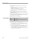
2. Set the AWG500–Series Waveform Generator controls and select the
waveform file:
a. Initialize the AWG500–Series Waveform Generator controls: Push
UTILITY (front–panel)!
System (bottom)!Factory Reset (side)!OK (side).
b. Select the waveform file: Load the MODE.WFM as referring to the
procedures on page 4–15.
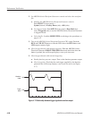
3. Turn on the AWG500–Series Waveform Generator CH1 output: Push the
RUN and CH1 OUT buttons so that the LEDs above the RUN button and
CH1 output connector light.
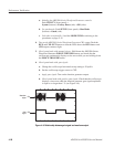
4. Check against limits: Check that the amplitude of the sine wave displayed on
the oscilloscope is 5 vertical divisions and that the waveform of one cycle
per 2 horizontal divisions is displayed.
5. End procedure: Disconnect the oscilloscope.
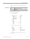
Equipment
required
Three 50ĂΩ coaxial cables, a BNC-T connector, a function generator,
and an oscilloscope.
Prerequisites The AWG500-Series Waveform Generator meets the prerequisites
listed on page 4-13.
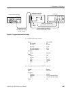
1. Install the test hookup and set test equipment controls:
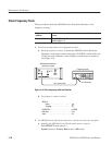
a. Hook up the oscilloscope: Connect the AWG500–Series Waveform
Generator CH1 output connector through the 50 W BNC coaxial cable to
the oscilloscope CH1 input connector.
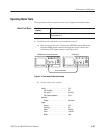
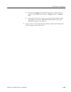
b. Hook up the function generator: Connect the AWG500–Series Wave-
form Generator TRIG IN connector though a 50 W BNC coaxial cable
and BNC–T connector to the function generator output connector, and
connect a 50 W BNC coaxial cable to BNC–T connector and the
oscilloscope CH2 input (see Figure 4–6).
Check Triggered Mode


