


Performance Verification
AWG510 & AWG520 Service Manual
4-59
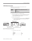
10 MHz Reference Input Tests
These procedures check the 10 MHz reference input function of the
AWG500–Series Waveform Generator.
Equipment
required
Two 50ĂΩ coaxial cables, a frequency counter, and a function
generator.
Prerequisites The AWG500-Series Waveform Generator meets the prerequisites
listed on page 4-13.
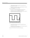
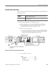
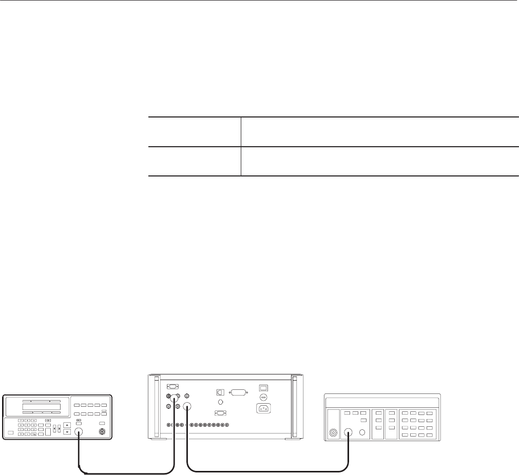
1. Install the test hookup and set test equipment controls:
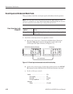
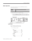
a. Hook up the frequency counter: Connect the AWG500–Series Waveform
Generator CLOCK OUT connector through the coaxial cable to the
input A connector on the frequency counter.
b. Hook up the function generator:
H Connect the AWG500–Series Waveform Generator 10 MHz REF IN
connector though a coaxial cable to the function generator output
connector (see Figure 4–29).
Frequency Counter
AWG500 Series Waveform
Generator rear panel
50 W coaxial cable
50 W coaxial cable
Function Generator (AFG310)
Figure 4-29: 10 MHz reference initial test hookup
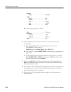
c. Set the frequency counter controls:
INPUT A
Coupling . ................... AC
FUNCTION ...................... AFREQ
Gate time . ...................... 0.2s
Level . ......................... 0V