


Adjustment Procedures
AWG510 & AWG520 Service Manual
5-7
Adjustment Instructions
This procedure adjusts Y330 on the A40 Clock board to set the AWG500 clock
frequency.
Equipment
Required
One frequency counter (Item 2)
One 50 W coaxial cable (Item 5)
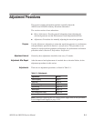
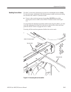
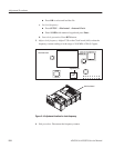
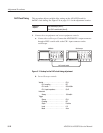
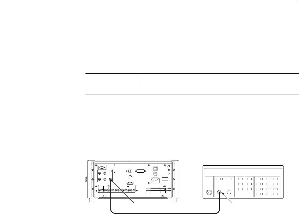
1. Connect the test equipment and set test equipment controls:
a. Connect the frequency counter: Connect the AWG500 Clock Output
connector through a BNC coaxial cable to the input A connector on the
frequency counter.
InputClock output
AWG500
Frequency counter
50 W coaxial cable
Figure 5-3: Hookup for the clock frequency adjustment
b. Set frequency counter controls:
Input A Coupling . ............. AC
Funciton .................... AFrequency
Gate Time . ................. 0.2s
Level . ..................... 0V
2. Set AWG500 controls:
a. Initialize AWG500 controls: Press UTILITY Ý System Ý Factory
Reset Ý OK.
b. Load waveform:
H Press SETUP Ý Waveform/Sequence Ý Load...
H Turn the general purpose knob to display the list of waveform files
and highlight the file MODE.WFM.
Clock Frequency