


Removal and Installation Procedures
AWG510 & AWG520 Service Manual
6-61
Do the
horizontal and
/or vertical sync
lock ok?
Power the generator off and
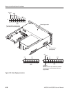
disconnect the cable from J125 on
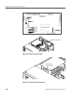
the A10/A11 Connector Board (see
Figure 6-33) then power back on.
Do pins 7
and 8 of J127 have
signals similar to
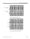
Figure 6-35?
Replace the monitor module
(page 6-50).
Power the AWG500 off and
disconnect the cable from J125 on
the A10/A11 Connector board (see
Figure 6-33) then power back on.
Is
TP102 on the
A10/A11 Connector
Board at +24 V
?
Does
pin 8 of J125
have a video signal with
the same levels as
in Figure
6-35?
Do pins
8 and 10 of J125
have signals similar
to Figure
6-35?
Do pins
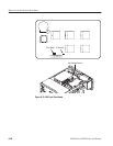
13 and 14 of the
VGA connector on the CPU
module (see Figure 6-34)
have signals
similar to Figure
6-35?
Replace the cable.
Are
the cables securely
installed in their sockets
and are the cables
ok?
Securely install
and/or replace
the cables.
Perform the power
supply module
troubleshooting
procedure 1
(page 6-57).
Does
J50 pin 7 on
the CPU board (see Figure
6-34) have a video
signal with the same levels
as in Figure
6-35?
Replace the CPU module
(page 6-44).
Replace the CPU module
or the Backplane Board
(page 6-44).
Is the
problem
fixed?
Yes Yes
Yes
Yes
Yes
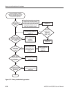
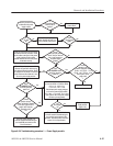
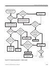
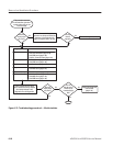
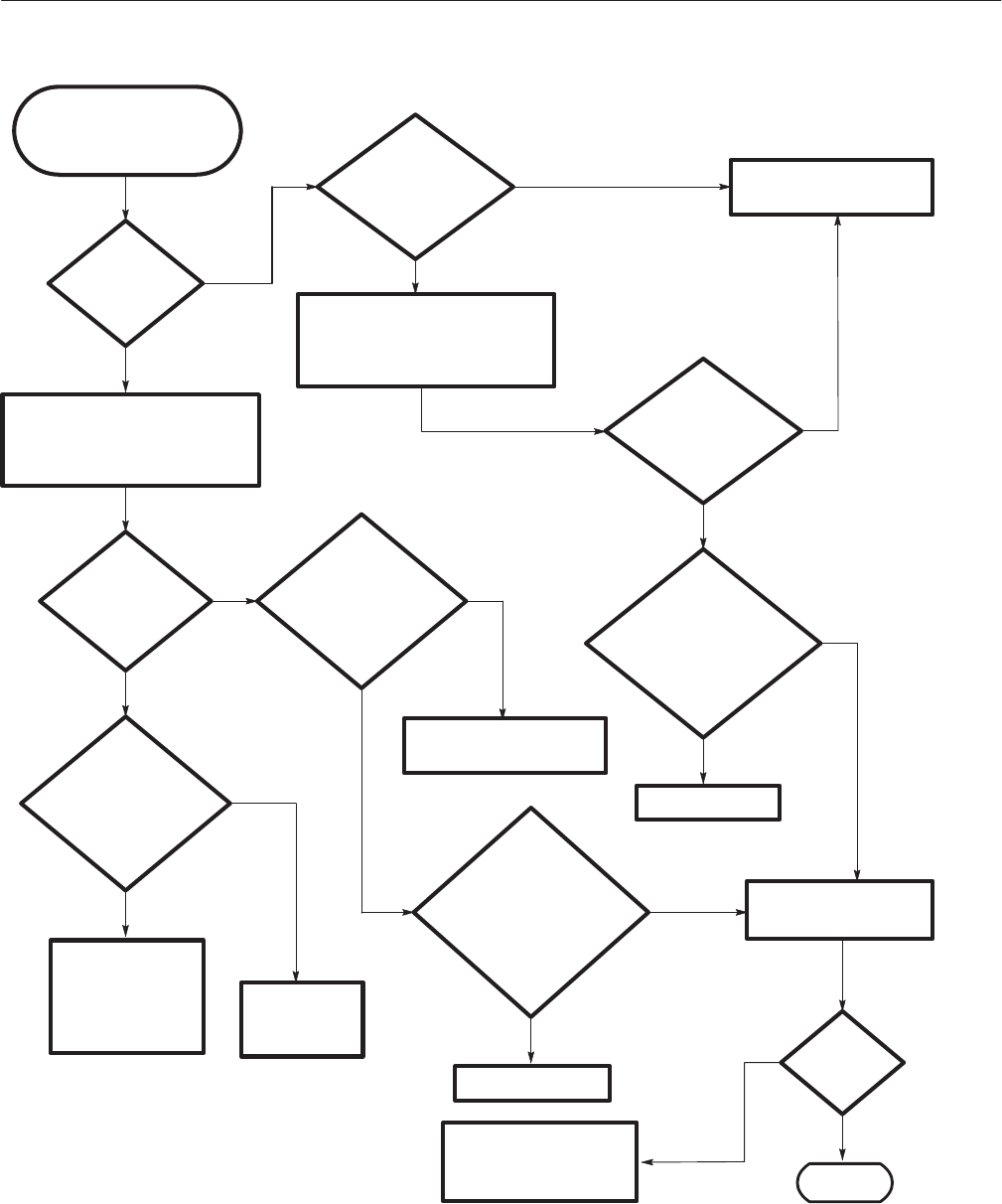
This procedure helps you
determine whether the monitor
module is bad.
No
No
No
No
No
Yes
Yes
No
Yes
No
No
Yes
Replace the cable.
No
Replace the monitor module
(page 6-50).
Done.
Figure 6-32: Troubleshooting procedure 3 Ċ Monitor module