--------
--------
--
------------
----
--------
--
-------
20
Engine
Tractors
,
Lawn
and
Gard
en -
110
and
112
30-10
Cylinder
Head
and
Valves
-
Tecumseh
SM-2059-(Apr-67)
INSTALLING
CARBURETOR
INSTALLING
H
YDRA
ULIC
LIFT
ASS M
BL
Y
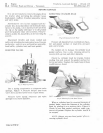
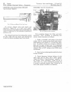
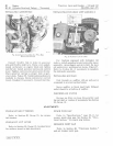
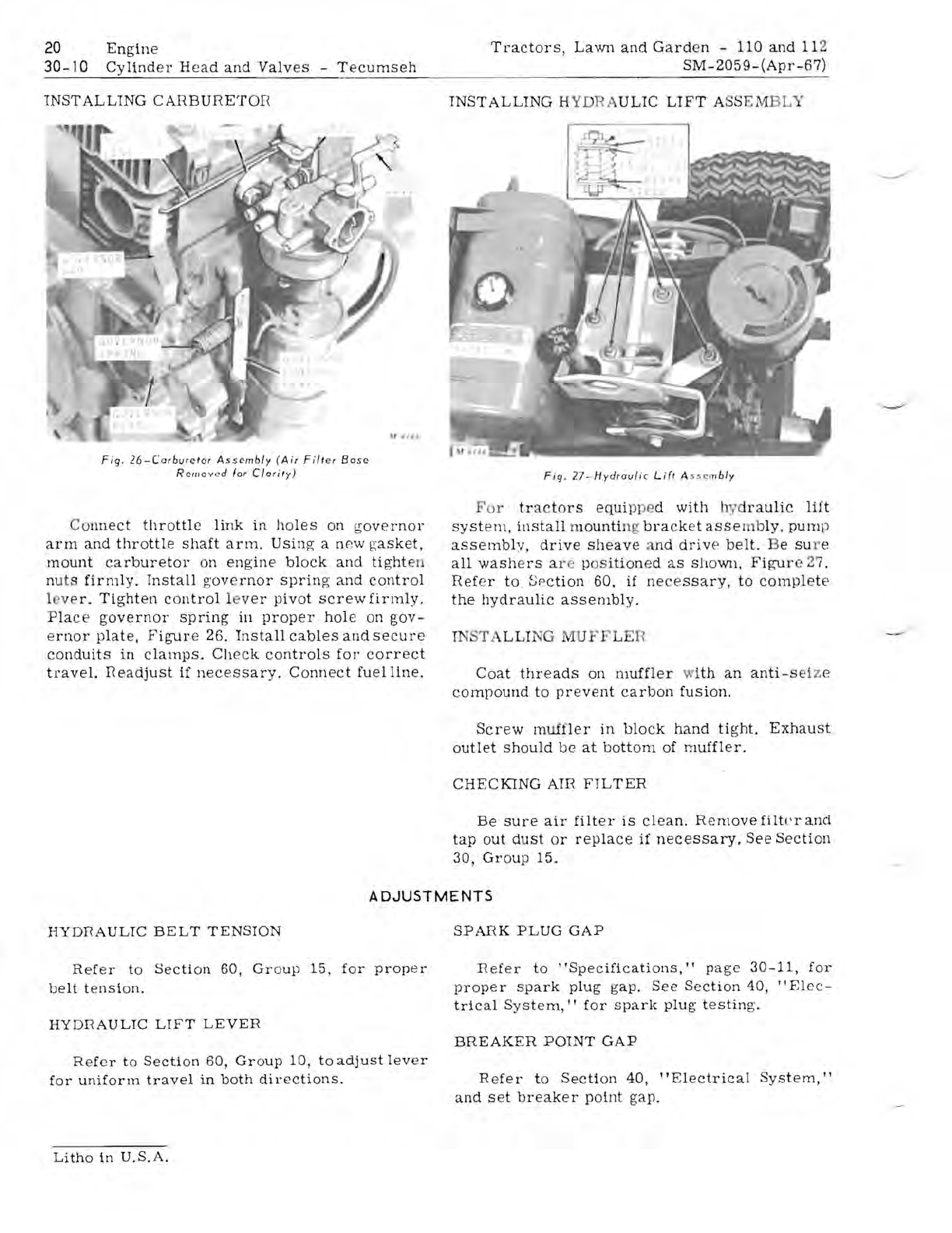
Fig.
26-Carburetor
Assembly
(Air
Filter
Base
Remov
ed
lor
Clarity)
Co
nnect
throttle
link
in
holes
on
governor
arm
and
throttle
shaft
arm.
Using
a npw
gasket,
mount
carburetor
on
engine
block
and
tight
en
nuts
firmly.
Install
g'
overnor
spring
and
control
1
ve
l'.
Tighten
control
le
ver
pivot
screw
firmly.
Place
governor
spring
in
proper
hole
on
gov-
ernor
plate,
Figure
26.
Install
cables
and
secure
conduits
in
clamps.
Check
controls
for'
correct
travel.
I<eadjust
if
necessary.
Connect
fuelllne.
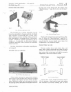
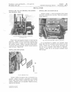
Fig.
27-Hydrau/ic
Lift
A
sse
m
bly
For
tr
a
ctors
equip
pe
d
with
hyd
raulic
lift
system,
install
mounti
ng
brack
et
asse
mb
ly
.
pum
p
assembly,
drive
sheave
a
nd
driv
e
belt.
Be
su
r e
all
washers
a r e p
OS
ition
ed
as
shown,
Figur
e 27 .
Refer
to
, Se
ction
60,
if
nec
e
ssary,
to
complete
the
hydraulic
assembly.
IN T
LLI
NG
dUFF
LER
Coat
threads
on
muffler
w
ith
an
anti-s
ei
z e
compound
to
prevent
carbon
fusion.
Screw
muffler
in
block
hand
tight.
Exhaust
outlet
should
be
at
bottom
of
muffler.
CHECKING
AIR
FILTER
Be
sure
air
filter
is
clean.
Removefilt!
'
rand
tap
out
dust
or
replace
if
necessary.
See
Section
30,
Group
15.
ADJUSTMENTS
HYDI<AULIC
BELT
TENSION
Refer
to
Section
60,
Group
15,
for
proper
belt
tension
.
HYDRAULIC
LIFT
LEVER
Refer
to
Section
60,
Group
10,
to
adjust
lev
er
for
uniform
travel
in
both
directions.
SPAnK
PLUG
GAP
Refer
to
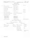
"Specifications,"
page
30-11,
for
proper
spark
plug
gap.
See
Section
40,
"Elec-
trical
System,
"
for
spark
plug'
testing.
BREAKER
POINT
GAP
R e
fer
to
Section
40,
"Electrical
System,"
and
set
breaker
po
tnt
gap.
Litho
in
U.S.A.


