50
Power
Train
Tractors,
Lawn
and
Garden
-
110
and
112
10-10
Clutch,
Brake
and
Variable
Speed
Drive
SM-2059-
(Apr-57)
REMOVING
VARIATOR
BEARING
AND
ARM
\ . .
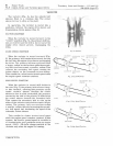
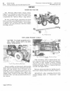
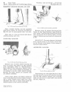
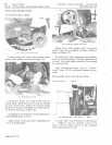
Fig.
13-Pr
es
sing
Varia
tor
Bearing
From Hvb
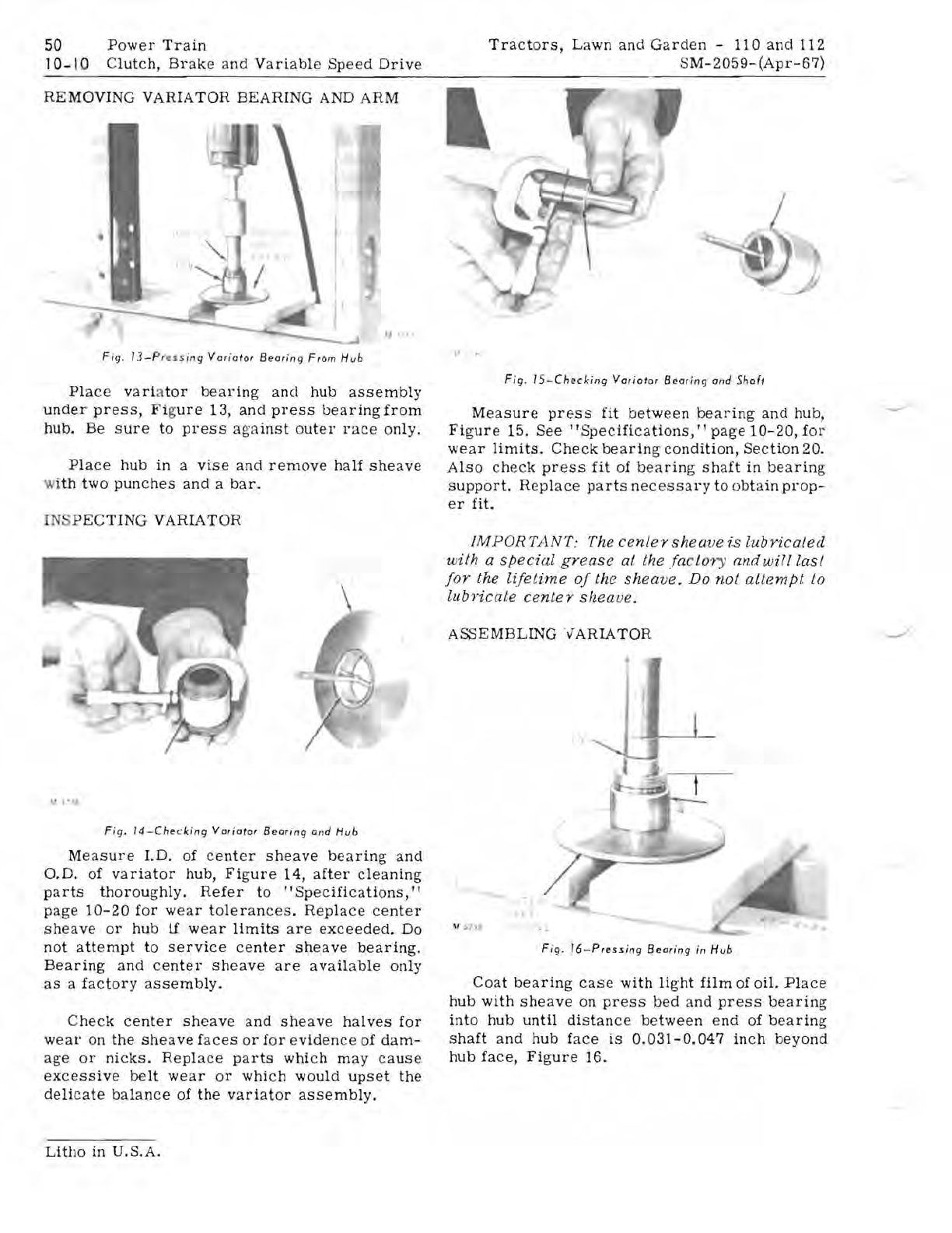
Place
vari
a
tor
bearing
ancl
hub
assembly
under
press,
Fi
g
ure
13,
and
press
bearing
from
hub.
Be
sure
to
press
against
outer
race
only.
Place
hub
in
a
vise
and
remove
half
sheave
w
ith
two
punches
and
a
bar.
I
NS
PECTING
VARIATOR
\1 • •
••
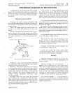
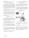
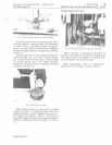
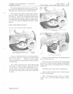
Fig.
14-Checking
Variator
Bearing
and
Hvb
Measure
J.D.
of
center
sheave
bearing
and
O.D.
of
variator
hub,
Figure
14,
after
cleaning
parts
thoroughly.
Refer
to
"Specifications,"
page
10-20
for
wear
tolerances.
Replace
center
sheave
or
hub
if
wear
limits
are
exceeded.
Do
not
attempt
to
service
center
sheave
bearing.
Bearing
and
center
sheave
are
available
only
as
a
factory
assembly.
Check
center
sheave
and
sheave
halves
for
wear
On
the
sheave
faces
or
for
evidence
of
dam-
age
or
nicks.
Replace
parts
which
may
cause
excessive
belt
wear
or
which
would
upset
the
delicate
balance
of
the
variator
assembly.
Litho
in
U.S.A.
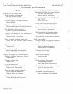
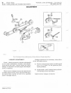
Fig.
IS-Checking
Varia
tor BearinC)
and
Shaft
Measure
press
fit
between
bearing
and
hub,
Figure
15.
See
"Specifications,"
page
10-20,
for
wear
limits.
Check
bearing
condition,
Section
20.
Also
check
press
fit
of
bearing
shaft
in
bearing
support.
Replace
parts
necessary
to
obtain
prop-
er
fit.
IMPORTANT:
The
center
sheave
is
lubricated
with
a
special
grease
at the
facto
ry
andwilllasl
for
the
lifetime
of
the
sheave.
Do
not
attempt
to
lubricate
center
sheave.
ASSEMBLING
V'ARIATOR
" .
1..
, .,
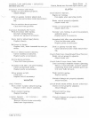
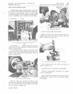
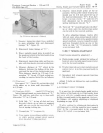
Fig.
16-Pressing
Bearing
in Hub
Coat
bearing
case
with
light
film
of
oil.
Place
hub
with
sheave
on
press
bed
and
press
bearing
into
hub
until
distance
between
end
of
bearing
shaft
and
hub
face
is
0.031-0.047
inch
beyond
hub
face,
Figure
15.


