Tractors,
Lawn
and
Garden
-
110
and
112
Hydraulic
System
60
SM-
2
059-
(Apr-
67)
Control
Valve
10-5
INST
ALLING
SPOOL
f I ' )
At
fjJ:
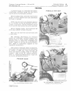
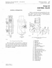
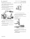
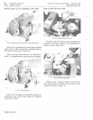
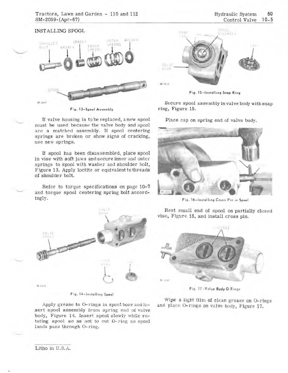
Fig.
13-Spool
Assembly
If
valve
housing
is
to
be
replaced,
a
new
spool
mus
t
be
used
becaus
e
the
valve
body
and
s
po
ol
are
a
matched
assembly.
If
spo
ol ce
nterin
g
spri
ngs
are
broken
or
show
signs
of
cracking,
u
se
ne
w s
prings.
If
spool
has
been
disa
ss
embl
ed,
place
sp
o
ol
in
vise
with
soft
j
aws
an
d s ec
ure
inn
er
a
nd
ou
ter
s p
rin
gs
to
spool
w
it
h
was
h
er'
nd
s
ho
ul
d
er
bo
lt,
F i
gu
r e 13.
Apply
loctite
or
equivalenttothreads
of
shoulder
bolt.
Refer
to
tor
que
specifications
on
p
age
10-7
and
torque
spool
c
entering
sp
r
in
g
bolt
a
cc
ord-
ingly.
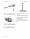
Fig.
14-ln
s
talli
ng S
pool
Apply g
reas
to
O-ri
ngs
in
sp
ool
bor
an
d
in-
se
r t
spoo
l
assembly
f
rom
spri
ng
end
of va
lve
bo
dy,
Figu
r e 14. Ins
er
t
spo
ol
sl
o
wl
y
whil
e
ro-
tati
ng
spo
ol s o
as
n
ot
to cut
O-rin
g
3S
sp
ool
la
n
ds
p
ass
th
roug
h
0-
ri
ng.
Litho
in .S.
A.
" r
II
Secure
spool
assembly
in
valve
body
with
sn
ap
ring,
Figure
15.
Pl
ace
ap
on
s
pring
end
of
valve
body.
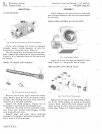
Fig
.
16-lnstalling
Cro
••
P in in
Spool
R
es
t s m
all
end
of
sp
ool
on
partially
cl
osed
vi e,
Figure
16,
and
in
s t
all
cross
pin.
Fi
g
17-
V
al
uc
Body
a
·R
lngs
Wi
pe
a
li
g
ht
fi
lm
of
cl
ea
n
gre
a
se
on
0-
r in
gs
an
d
pl
ace
O-rings
on
va
lv
e body, F i
gur
e 17.
Y
--
--:
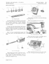
Fig.
IS-Installing
Snap
Ring


