60
Hydraulic
System
Tractors,
Lawn
and
Garden
-
110
and
112
10-6
Control
Valve
SM-2059-
(Apr-67)
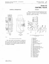
INSTALLING
VALVE
ASSEMBLY
ON
PUMP
INST
ALLING
ON
TRACTOR
/
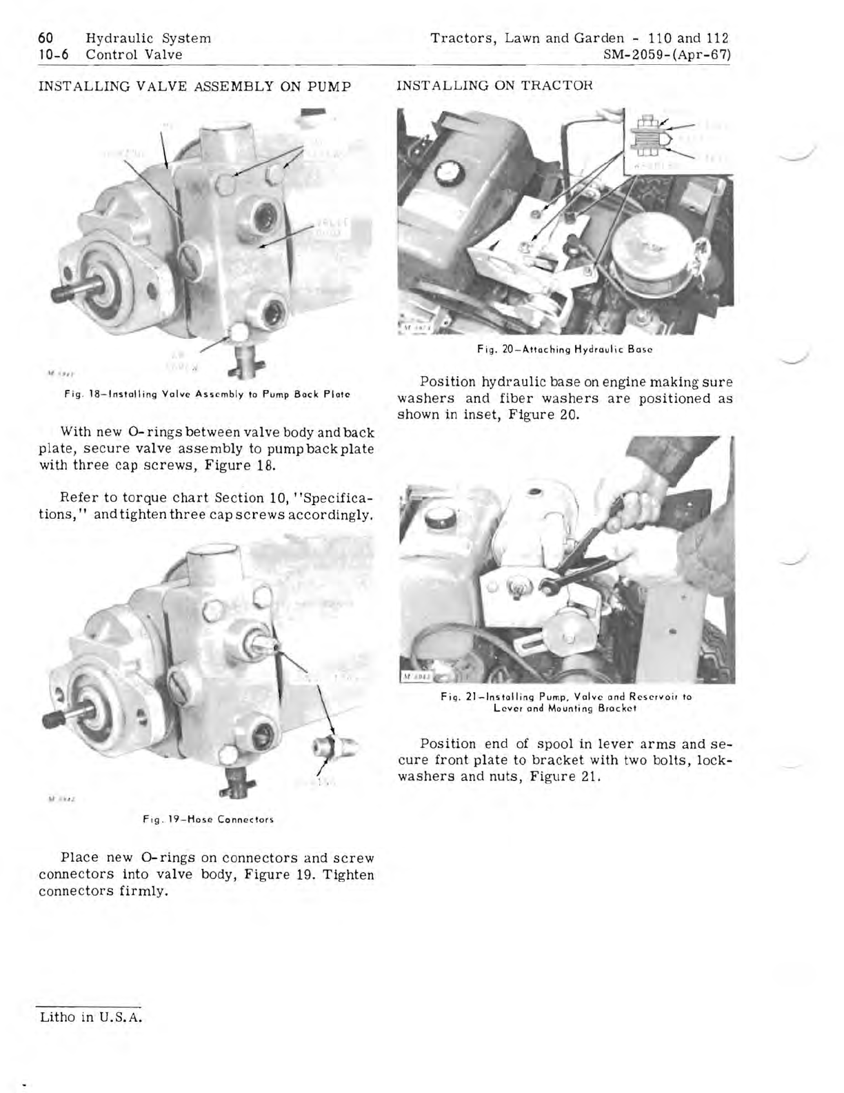
Fig
.
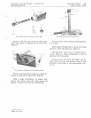
18-lnstalling
Valve
Assembly
to
Pump
Back
Plate
With
new
0-
rings
between
valve
body
and
back
plate,
secure
valve
assembly
to
pump
back
plate
with
three
cap
screws,
Figure
18.
Refer
to
torque
chart
Section
10,
"Specifica-
tions,
I I
and
tighten
three
cap
screws
accordingly.
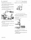
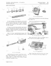
Fig.
20-Attaching
Hydraulic
Base
Position
hydraulic
base
on
engine
making
sure
washers
and
fiber
washers
are
positioned
as
shown
in
inset,
Figure
20.
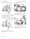
Fig.
21-ln5tolliog
Pump,
Valve
and
Reservoir
to
Level
and
Mouotiog
Bracket
Position
end
of
spool
in
lever
arms
and
se-
cure
front
plate
to
bracket
with
two
bolts,
lock-
washers
and
nuts,
Figure
21.
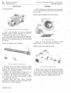
Fig
.
19-Hose
Connectors
Place
new
0-
rings
on
connectors
and
screw
connectors
into
valve
body,
Figure
19.
Tighten
connectors
firmly.
Litho
in
U.S.A.


