Tractors,
Lawn
and
Garden
-
110
and
112
Power
Tr
a
in
50
SM-2059-(Apr-67)
Clutch,
Brak
e a
nd
Vari
a
ble
Speed
Driv
e
10-11
I',
,
I
J'
,
ttA \
.11
Fi
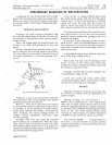
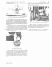
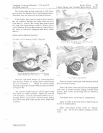
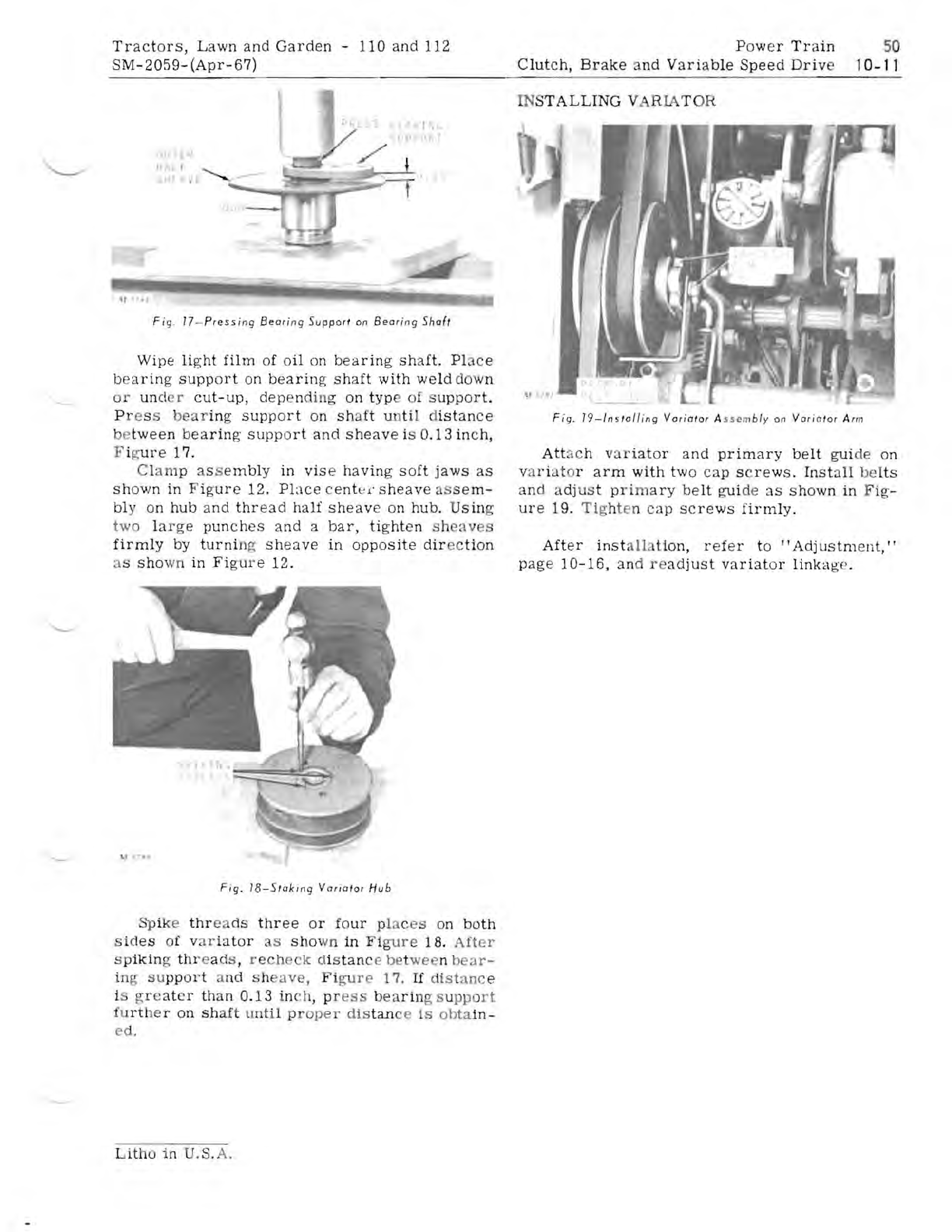
g. 17 -
Pre
ssing
Be
ar in g
Support
on
Bearin
g
Shaft
Wipe
li
ght
film
of
oil
on
bearing
shaft.
Pl
a
ce
bear
ing
support
on b
ea
ring
shaft
with
weld
down
or unci r
cut-up,
depend
in
g
on
typ
e
of
s
upp
o
rt.
P r es s
bear
ing
support
on
sh
aft
un
ti
l d
istanc
e
be
tween
bea
ring
support
and
sheave
is 0
.13
in
ch,
F ig
ure
17.
Clam p
as
s
embly
in
vis
e
hav
ing
soft
jaws
as
shown
in F ig
ur
e 12. PLl
ce
ce
nt
e:
c
sheave
as
se
m-
bly
on
hub
and
thr
ead
half
sheave
on
hub.
Usin
g
two
la
rge
punche
s
and
a
bar,
tight
en s h
eav
s
firmly
by
turni
n
cr
sh
ea
ve
in
opposite
dir
ec
ti
on
as
sho
wn
in
Fi
gure
12.
IN
STALL
ING V R
LA
T
OR
F
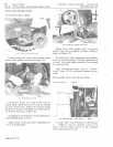
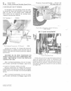
ig
.
19-1nsloll
i
ng
Vor
ia
tor
A
ss"m
bl
y on
Vari
a
tor
Ar
m
Att
a ch va
ria
tor a
nd
primary
belt
gui
de on
va
riat
or
arm
with
two
cap
s c
rews.
In
stall
be
lts
an
d adjus t p
rimary
be
lt
guid
e
as
shown
in F
ig-
ur
e 19.
Tig
ht en
cap
screws
firmly.
After
inst
all
tion,
r
efe
r
to
"Adjustment,"
page
10-16,
an
d r e
adjust
variator
linka
ge.
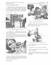
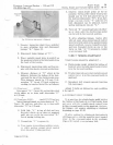
Fig.
18
-Slok
ing
Vo
rioto
r
Hub
Spike
thr
e
ds
thr
ee
or
fo
ur
plac
es
on
both
side
s of v
ar
i:.1
t
or
as
sho
wn
in
Fi
gure
18.
After
s p
ikin
rr
th
r eads , r ec he
ck
dis
tan
ce
be
t
wee
n
bear-
in
g u
ppo
r t a
nd
s h
av
e,
Fi
gure
17.
If
dis t
anc
e
is gr e
at
er
than
0.13
in
ch
, pr
ess
b
ea
rin
g s u
pport
fu
rt
he r
on
sh
aft
u
ntil
pr
oper
dis
tan
ce
is
obta
in-
e
d.
Litho
in U.S. A.


